An on-site part angle measuring device and method

An angle measurement device and parts technology, applied in the direction of measuring devices, optical devices, instruments, etc., can solve the problems of difficult identification and deviation of photographers, and achieve the effect of easy angle measurement, easy observation, and convenient remote diagnosis

Active Publication Date: 2020-06-26
GUANGXI YUCHAI MASCH CO LTD
View PDF10 Cites 0 Cited by
  • Summary
  • Abstract
  • Description
  • Claims
  • Application Information

AI Technical Summary

Problems solved by technology

However, the problem with this method is that when the optical axis of the shooting device is not perpendicular to the object to be photographed, there will be a deviation between the measured angle value and the actual value, which is difficult for the photographer to identify

Method used


Image

  • An on-site part angle measuring device and method
  • An on-site part angle measuring device and method
  • An on-site part angle measuring device and method

Examples


Embodiment 1

[0027] The on-site part angle measuring device according to the preferred embodiment of the present invention includes: a magnetic base and a cylindrical structure, the cylindrical structure is vertically arranged on the magnetic base, and is connected with the magnetic base as an integral structure; wherein, the lower end of the cylindrical structure is close to the cylinder A light-transmitting hole is provided at the connection portion between the cylindrical structure and the magnetic base 1, and the light-transmitting hole penetrates the cylindrical structure.

[0028] In the above solution, the diameter of the light-transmitting hole is smaller than the diameter of the cylindrical structure. The cylindrical structure is arranged vertically at the center of the magnetic base.

Embodiment 2

[0030] Such as Figure 2 to Figure 4 As shown, the on-site component angle measuring device according to the preferred embodiment of the present invention includes: a magnetic base 1 and a cylindrical structure 2, the cylindrical structure 2 is vertically arranged on the magnetic base 1, and is connected with the magnetic base 1 as an integral structure. Preferably, the cylindrical structure 2 is vertically arranged at the center of the magnetic base 1 . Wherein, the lower end of the cylindrical structure 2 is provided with a light-transmitting hole 3 near the connection between the cylindrical structure 2 and the magnetic base 1, the light-transmitting hole 3 runs through the cylindrical structure 2, and the diameter of the light-transmitting hole 3 is smaller than that of the cylindrical structure 2 diameter of. Cross wires 4 are arranged in both the inner hole of the upper end surface and the inner hole of the lower end surface of the cylindrical structure 2 .

[0031] In...

Embodiment 3

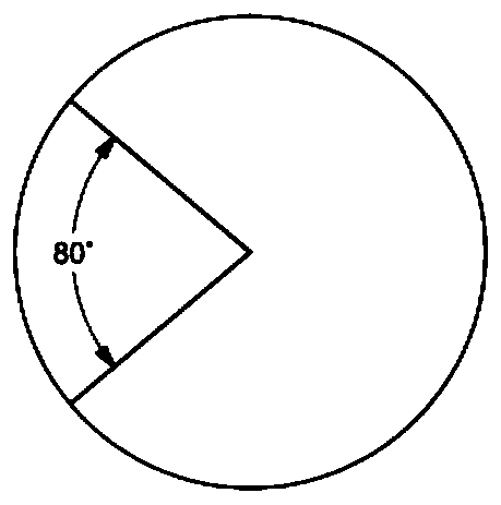
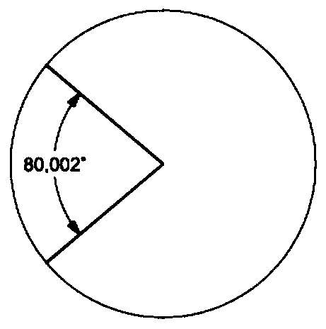
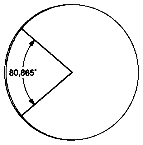
[0033] Such as Figure 6 As shown, the present invention also provides a method for on-site part angle measurement, including the following steps: step 601: attach the on-site part angle measurement device to the part to be measured through a magnetic base; step 602: connect the optical axis of the shooting device to the on-site The axis of the cylindrical structure of the part angle measuring device is kept aligned; step 603: observe the coaxiality of the inner hole of the upper end surface of the cylindrical structure and the inner hole contour of the lower end surface to determine whether the optical axis of the shooting device is perpendicular to the part to be measured; step 604: When it is observed that the part to be tested is perpendicular to the optical axis of the photographing device, take a photo of the part to be tested to obtain a photo to be tested; and Step 605: Measure the corresponding angle in the photo to be tested by software.


PUM


Abstract

The invention discloses an on-site part angle measuring device and method; the device comprises a magnetic base and a cylindrical structure arranged on the magnetic base vertically and connected withthe same to form an integral structure. A light transmitting hole which penetrates the cylindrical structure is arranged at the position, close to a connection portion of the cylindrical structure andthe magnetic base, of the lower end of the cylindrical structure. By means of increasing axial distance, the device is easy for recognizing and adjusting angle deviation, deviation of perpendicularity between optical axis of photographing equipment and a photographed object is ensured to be within a small range, errors when related angle of pictures acquired by the photographing equipment is measured through software are ensured within an acceptable range, and convenience is brought to on-site part angle measuring.

Description

technical field [0001] The invention relates to the technical field of mechanical installation and maintenance, in particular to an on-site part angle measuring device and method. Background technique [0002] In some mechanical transmission devices, the installation angle between parts is required to follow certain requirements. In particular, in the engine gear train, there are strict requirements on the installation angles between the transmission gears. [0003] In assembly and maintenance work, it is often necessary to confirm the angle of the above-mentioned parts. In general operations, it is usually judged whether the angle of the part is correct by comparing it with the characteristic parts of the surrounding parts. This method has low effect and poor accuracy. , while tools such as protractors often fail to measure because parts are often not planar and vary in size. [0004] At present, digital cameras and mobile phones are widely used, and the image sensors use...

Claims


Application Information

Patent Timeline
Patent Type & Authority Patents(China)
IPC IPC(8): G01B11/26
CPCG01B11/26
Inventor 孙步武
Owner GUANGXI YUCHAI MASCH CO LTD
Why Eureka
Try Eureka