Video area removal tampering detection method and device

A tampering detection and video technology, applied in the field of video area removal tampering detection, can solve the problems of low detection accuracy and low applicability, and achieve the effect of high detection result accuracy, strong applicability, and improved training results.

Pending Publication Date: 2019-04-19
GUANGDONG UNIV OF TECH
View PDF8 Cites 8 Cited by
  • Summary
  • Abstract
  • Description
  • Claims
  • Application Information

AI Technical Summary

Problems solved by technology

[0004] The embodiment of the present application provides a method and device for video region removal and tampering detection,

Method used


Image

  • Video area removal tampering detection method and device
  • Video area removal tampering detection method and device
  • Video area removal tampering detection method and device

Examples


Embodiment Construction

[0055] In order to enable those skilled in the art to better understand the solution of the present application, the technical solution in the embodiment of the application will be clearly and completely described below in conjunction with the accompanying drawings in the embodiment of the application. Obviously, the described embodiment is only It is a part of the embodiments of this application, not all of them. Based on the embodiments in this application, all other embodiments obtained by persons of ordinary skill in the art without making creative efforts belong to the scope of protection of this application.

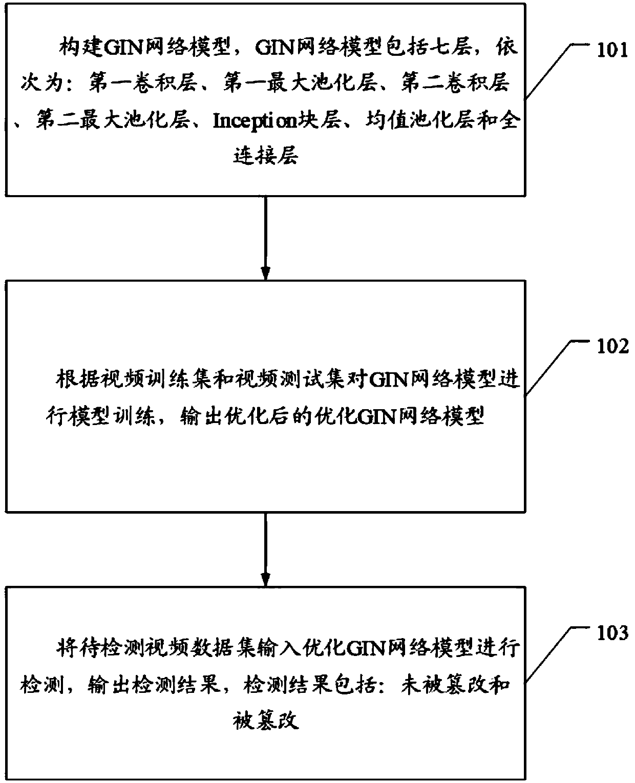
[0056] For ease of understanding, see figure 1 , a method for detecting video area removal and tampering in the embodiment of the present application, comprising:

[0057] Step 101, constructing the GIN network model, the GIN network model includes seven layers, which are: the first convolutional layer, the first maximum pooling layer, the second convolutional lay...


PUM


Abstract

The invention discloses a video area removal tampering detection method and device. According to the method, the GIN network model of the seven-layer structure is constructed, the GIN network model istrained and optimized, the video data set to be detected is input into the optimized GIN network model to be detected, the detection result is high in accuracy and applicability, and the technical problems that an existing video tamper detection method is not high in detection accuracy and low in applicability are solved.

Description

technical field [0001] The present application relates to the technical field of multimedia information security, and in particular to a method and device for detecting video region removal and tampering. Background technique [0002] With the rapid development of computer and Internet technology, more and more various types of video dissemination software and video editing software are widely used, and the methods and ways of tampering with videos are becoming more and more diverse, while protecting personal privacy Video tampering will play a negative role in aspects such as legal and legal evidence collection. Therefore, the research on video tampering detection technology is an important direction for those skilled in the art. [0003] The method of video tampering detection in the prior art is to analyze the video and extract the frame information, and compare the frame information with the comparison frame information in the database to realize the detection of the tam...

Claims


Application Information

Patent Timeline
IPC IPC(8): G06K9/00G06K9/62G06N3/04G06N3/08
CPCG06N3/08G06V20/40G06N3/045G06F18/24G06F18/214
Inventor 翁韶伟易林危博叶武剑刘怡俊张子文
Owner GUANGDONG UNIV OF TECH
Why Eureka
Try Eureka