Core for winding, method for producing the same, and electronic component with winding

A manufacturing method and winding technology, which can be applied to inductors with magnetic cores, transformer/inductor components, electrical components, etc. cost effect

Active Publication Date: 2021-05-14
MURATA MFG CO LTD
View PDF13 Cites 0 Cited by
  • Summary
  • Abstract
  • Description
  • Claims
  • Application Information

AI Technical Summary

Problems solved by technology

[0011] In addition, if the core body is dip-dyeed obliquely with respect to the conductor paste, the electrode portion can be increased only on the outer end face side, but in this case, each end of the core body needs to be dip-dyeed separately, so mass productivity is further deteriorated.

Method used


Image

  • Core for winding, method for producing the same, and electronic component with winding
  • Core for winding, method for producing the same, and electronic component with winding
  • Core for winding, method for producing the same, and electronic component with winding

Examples


no. 1 approach

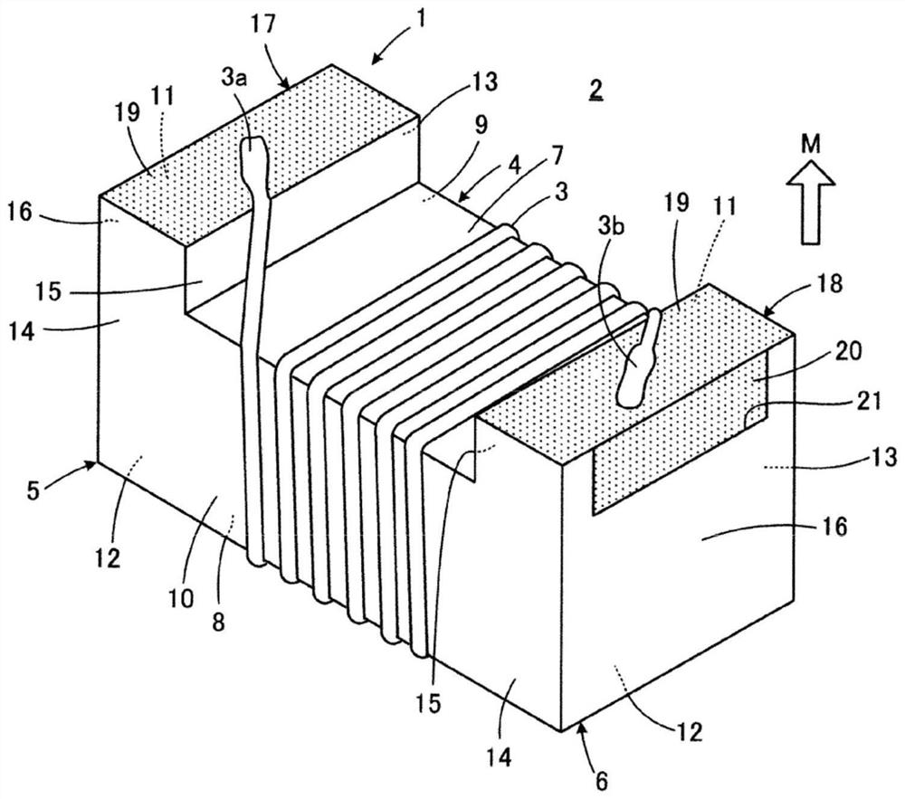
[0068] First, refer to figure 1 , the electronic component 2 with a winding provided with the winding core 1 according to the first embodiment of the present invention will be described. exist figure 1 In , the electronic component 2 with a winding is shown with the bottom surface facing the mounting substrate facing upward. The illustrated electronic component 2 with a winding is, for example, a coil component having a single coil.

[0069] The winding core 1 included in the electronic component 2 with the winding has the winding core 4 on which the winding 3 is arranged, the first flange 5 and the second flange 6, and the first terminal electrode 17 and the second terminal electrode 18. . The core 4 has a longitudinal direction, and the first and second flanges 5 and 6 are respectively provided at first and second ends opposite to each other in the longitudinal direction of the core 4 .

[0070] The winding core 1 is made of a non-conductive material, more specifically, ...

no. 2 approach

[0104] Next, refer to Figure 10 , the winding core 1a according to the second embodiment of the present invention will be described. exist Figure 10 In the following figures, for the Figure 1 to Figure 9 Components corresponding to the shown components are denoted by the same reference signs, and redundant descriptions are omitted.

[0105] In the above-mentioned first embodiment, the winding core part top surface 8 in the winding core body 1 is the same surface as the flange part top surface 12, but in the second embodiment, the characteristic feature is that the winding core body 1a The top surface 8 of the core portion is lower than the top surface 12 of the flange portion, that is, the top surface 8 of the core portion is closer to the mounting substrate than the top surface 12 of the flange portion. If such a structure is adopted, winding 3 (refer to figure 1) can not protrude outward from the flanges 5 and 6 on the core top surface 8 side. Therefore, the winding ...

no. 3 approach

[0110] Next, refer to Figure 12 , the winding core 1b according to the third embodiment of the present invention will be described.

[0111] The third embodiment is first characterized in that the winding core portion top surface 8 is lower than the flange portion top surface 12 in the winding core body 1 b as in the above-mentioned second embodiment. Thus, winding 3 (refer to figure 1 ) can not protrude outward compared with the flanges 5 and 6 on the core top surface 8 side.

[0112] In the above-mentioned second embodiment, the first and second winding core side surfaces 9 and 10 of the winding core 1a are respectively the same as the first and second flange side surfaces 13 and 14, but the third Another characteristic of the embodiment is that the first and second winding core side surfaces 9 and 10 of the winding core 1 b are lower than the first and second flange side surfaces 13 and 14 , respectively. In other words, in the third embodiment, the first and second cor...


PUM


Abstract

The present invention relates to a winding core, a manufacturing method thereof, and an electronic component with a winding. The winding core body including the terminal electrodes formed extending from the bottom surface to the end surface adjacent to the bottom surface can be manufactured with high mass productivity. The winding core includes: a winding core extending along the longitudinal direction; a first flange and a second flange respectively provided at the first end and the second end of the winding core in the longitudinal direction. Two end portions; and at least one terminal electrode is provided on each of the above-mentioned first flange portion and the above-mentioned second flange portion. When the outer surface of the edge portion facing the opposite side of the winding core portion, that is, the outer surface, is formed on the outer end surface, a concave portion reaching the bottom surface of the first flange portion is formed, and the terminal provided on the first flange portion The electrode has a bottom surface electrode portion composed of a film-shaped conductor along the bottom surface of the first flange portion, and an end surface electrode portion composed of a conductor filling the concave portion and in contact with the bottom surface electrode portion.

Description

technical field [0001] This publication relates to a winding core, a method of manufacturing the same, and an electronic component with a winding including the winding core, and particularly relates to improvements in the form of terminal electrodes provided on the winding core and the method of forming the terminal electrodes. Background technique [0002] For example, the subject of the technology described in Japanese Patent Application Laid-Open No. 2003-243226 (Patent Document 1) is to provide easy mass production of cores, a small variation in inductance value, and a printed circuit board when mounted on a printed circuit board. A winding-type electronic component in which the fixing strength of a substrate is also stabilized, and a method for manufacturing the same. In order to solve this problem, Patent Document 1 describes the following configuration. [0003] The core body is cut into a substantially rectangular shape by cutting a sheet made of a magnetic material...

Claims


Application Information

Patent Timeline
Patent Type & Authority Patents(China)
IPC IPC(8): H01F17/04H01F41/02
CPCH01F17/04H01F41/02H01F17/045H01F27/292H01F41/0246H01F27/2823H01F27/40H01F27/245H01F41/0233H01F27/29
Inventor 森长哲也
Owner MURATA MFG CO LTD
Why Eureka
Try Eureka