H-slot coupled feeding circularly polarized antenna

A technology of circularly polarized antennas and coupled feeding, which is applied in the directions of antennas, antenna couplings, and antenna parts, can solve the problems of difficult antennas, large size of coupled feeding antennas, conformal and fixed, etc., to prevent antenna movement, Improved isolation and miniaturization

Active Publication Date: 2019-04-19
SPACE STAR TECH CO LTD
View PDF17 Cites 2 Cited by
  • Summary
  • Abstract
  • Description
  • Claims
  • Application Information

AI Technical Summary

Problems solved by technology

However, the size of the coupled feed antenna is large, and it is difficult to conform and fix the antenna with the carrier

Method used


Image

  • H-slot coupled feeding circularly polarized antenna
  • H-slot coupled feeding circularly polarized antenna
  • H-slot coupled feeding circularly polarized antenna

Examples


Embodiment Construction

[0022] Embodiments of the present invention will be described below in conjunction with the accompanying drawings. It should be pointed out that the following embodiments are only illustrative rather than restrictive, and those skilled in the art can combine or replace one or more embodiments according to the teaching of the present invention, so as to achieve different technical effects.

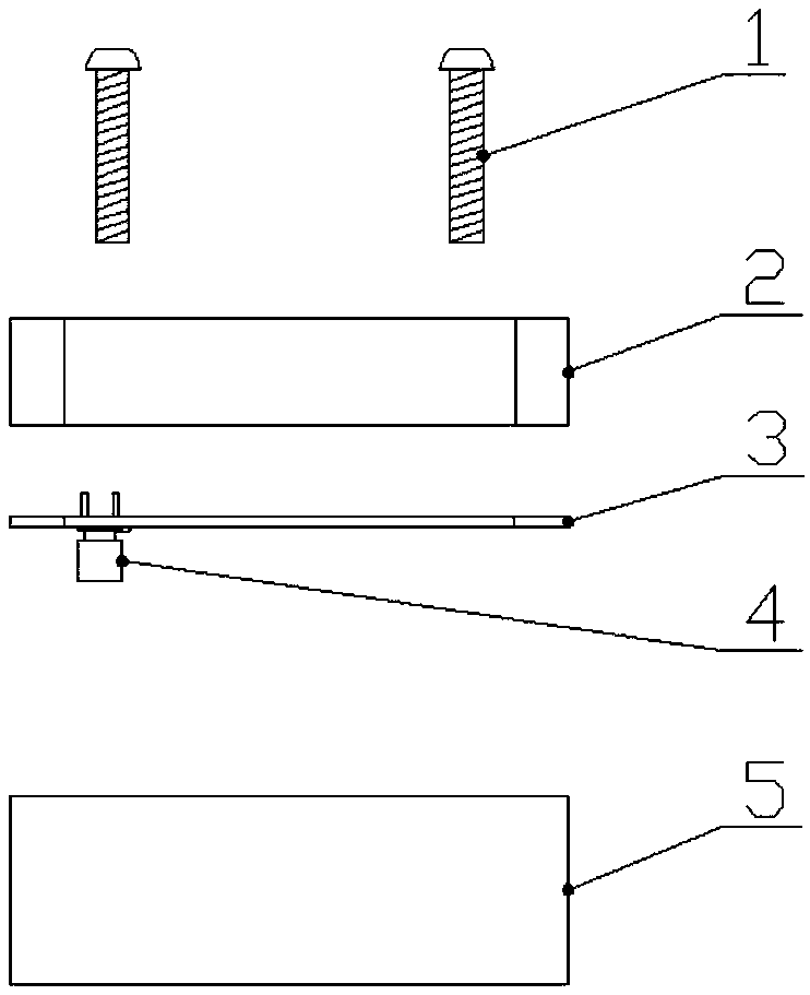
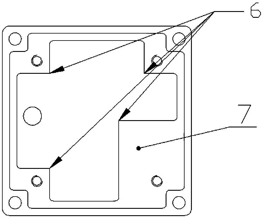
[0023] figure 1 It is a schematic diagram showing the structure and installation of the H-slot coupling feed circularly polarized antenna according to the embodiment of the present invention. The H-slot coupled feed circularly polarized antenna consists of five parts: antenna unit, feed network, antenna base, nylon screw and radio frequency connector. Specifically, such as figure 1 and figure 2 As shown in , the H-slot coupled feed circularly polarized antenna of the present invention includes: nylon screw 1, antenna unit 2, antenna feed network 3, radio frequency connector 4, square an...


PUM


Abstract

The invention discloses an H-slot coupled feeding circularly polarized antenna, which comprises a square antenna base (5), an antenna unit and an antenna feed network (3) which are arranged on the square antenna base (5), and a radio frequency connector (4) fixed under the square antenna base (5). The H-slot coupled feeding circularly polarized antenna disclosed by the invention has the advantagesof wide bandwidth, small size, reliable structure and fixation, light weight and the like, and can effectively solve the problems of large size, complicated installation and the like.

Description

technical field [0001] The present invention relates generally to the field of data link communication antennas. More specifically, the present invention relates to S-band broadband circularly polarized antennas. Background technique [0002] The data link antenna is usually installed on the surface of the carrier and completes the data transmission, which often requires high gain, wide bandwidth and miniaturized design. The traditional microstrip antenna has the characteristics of easy conformality, etc., but the bandwidth of the traditional microstrip antenna is only about 4%, and it is difficult to achieve a wider bandwidth. The coupled-fed microstrip antenna can effectively widen the bandwidth, and the bandwidth reaches about 15%. However, the size of the coupled feed antenna is large, and it is difficult to conform and fix the antenna with the carrier. Contents of the invention [0003] One of the technical problems that the present invention aims to solve relates ...

Claims


Application Information

Patent Timeline
Patent Type & Authority Applications(China)
IPC IPC(8): H01Q1/12H01Q1/50H01Q1/52
CPCH01Q1/12H01Q1/50H01Q1/521
Inventor 李航张文杰刘洋
Owner SPACE STAR TECH CO LTD
Why Eureka
Try Eureka