
Method for mounting rotors of electrical machines

A technology of rotors and installation positions, applied in the manufacture of motor generators, stator/rotor bodies, electrical components, etc.

Inactive Publication Date: 2019-04-19
DR ING H C F PORSCHE AG
View PDF8 Cites 0 Cited by
  • Summary
  • Abstract
  • Description
  • Claims
  • Application Information

AI Technical Summary

Problems solved by technology

[0009] However, the provision of balancing disks has the disadvantage that on the one hand the overall axial length of the rotor is increased and on the other hand the mass of the rotor is increased

Method used


Image

  • Method for mounting rotors of electrical machines

Examples


Embodiment Construction

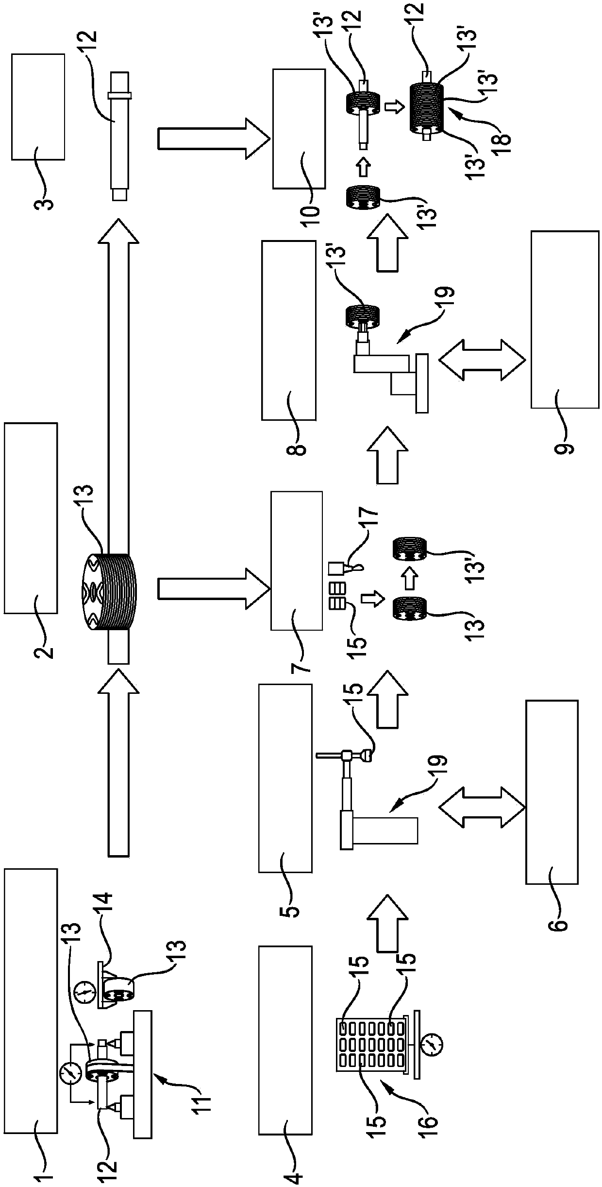
[0029] The invention relates to a method for installing a motor rotor. Each rotor of the motor to be installed has: a shaft, a segmented plate group with magnet sleeves arranged on the shaft, preferably composed of a plurality of plate group segments, and a magnet in the plate group or plate group segment Magnets arranged in sets. The magnets form pole pairs.

[0030] Refer to below figure 1 The diagram shown in the figure describes the method for installing the rotor of the motor according to the present invention, and is especially used in a preferred case, where the plate group of the corresponding rotor is composed of a plurality of plate group segments.

[0031] See first figure 1 The box 1 of, provides a shaft 12 for the motor rotor to be installed, in which at least one shaft 12 is measured, preferably for determining the imbalance of this shaft 12.

[0032] In addition, in figure 1 A plate group section 13 is provided for the segmented plate group in the box 1 of, wherei...


PUM


Abstract

Method for mounting rotors (18) of electrical machines, each rotor (18) having a shaft (12), a laminated core arranged on the shaft, preferably segmented laminated core with magnetic pockets and magnets (15) arranged in the magnetic pockets, having at least the following steps: providing shafts (12) and measuring at least one shaft (12); providing laminated cores or laminated core segments (13) and measuring at least one laminated core or at least one laminated core segment (13); providing a plurality of magnets (15) and measuring the magnets (15); for each rotor to be manufactured (18), selecting one or more laminated core segments (13), selecting a shaft (12) and selecting magnets (15); for each rotor to be manufactured (18), calculating mounting positions for the selected magnets (15) in the magnetic pockets of the selected laminated core or sheet package segments, and preferably calculating a mounting position for the selected sheet metal package or for the selected laminated coresegments (13); mounting the magnets (15) in the calculated mounting positions in the magnet pockets of the laminated core or the laminated core segments (13); and mounting the laminated core or the laminated core segments (13) on the shaft (12) in the preferably calculated mounting position.

Description

Technical field [0001] The invention relates to a method for installing a motor rotor. Background technique [0002] The rotor of the motor has a shaft, a plate group positioned on the shaft, and a magnet positioned in the magnet sleeve of the plate group. The magnets form pole pairs. The plate group of the rotor of the motor may be formed as a segmented plate group composed of plate group segments positioned side by side or positioned one behind the other in the axial direction of the shaft. [0003] Even in the generally symmetrical configuration of the rotor, manufacturing deviations of the individual components of the rotor can cause imbalance. If the unbalance exceeds the limit value, undesirable vibration, noise and premature failure will be generated during the operation of the motor. [0004] In order to compensate the imbalance of the rotor of the electric machine, it is also known in practice to balance the rotor. To this end, the imbalance is measured and the balance i...

Claims


Application Information

Patent Timeline
IPC IPC(8): H02K15/03
CPCH02K15/03H02K1/276H02K15/165
Inventor J·施托尔G·米希纳J·弗莱舍尔M·彼得
Owner DR ING H C F PORSCHE AG
Learn More