Electrical high-branch shears

An electric technology for high branch shears, applied in the field of pruning shears, can solve the problems of inability to cut high branches, inconvenient use, hidden safety hazards, etc., and achieve the effect of stable work, convenient use and reliable pruning

Active Publication Date: 2019-04-23
ZHEJIANG DONGQIAO PRECISION MACHINERY CO LTD
View PDF8 Cites 1 Cited by
  • Summary
  • Abstract
  • Description
  • Claims
  • Application Information

AI Technical Summary

Problems solved by technology

[0002] Pruning shears are a commonly used pruning tool at present. The current pruning shears are usually manual pruning shears. Although the structure is simple, the pruning is relatively laborious, especially for the pruning of taller branches, often with the help of long ladders. Climbing, inconvenient to use, and there is the problem of potential safety hazard; For this reason, some present inventors fix the pruning shears on the upper end of the high branch bar, so that the pruning personnel can stand on the ground by holding the lower end of the high branch bar for comparison. High branches are pruned, but the pruners need to manually operate the pruning shears fixed on the upper end of the high branches at the lower end of the high branches to achieve pruning. twig problem
[0003] On the other hand, the pruning shears on the current market are often all single-purpose, only suitable for pruning higher branches, or only suitable for pruning lower branches

Method used


Image

  • Electrical high-branch shears
  • Electrical high-branch shears
  • Electrical high-branch shears

Examples


specific Embodiment 1

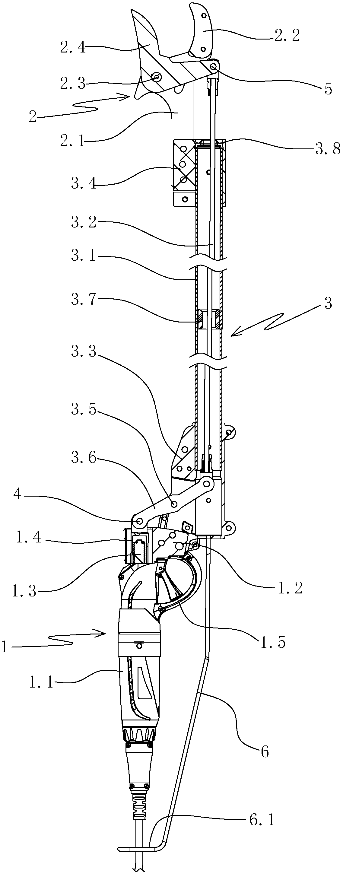
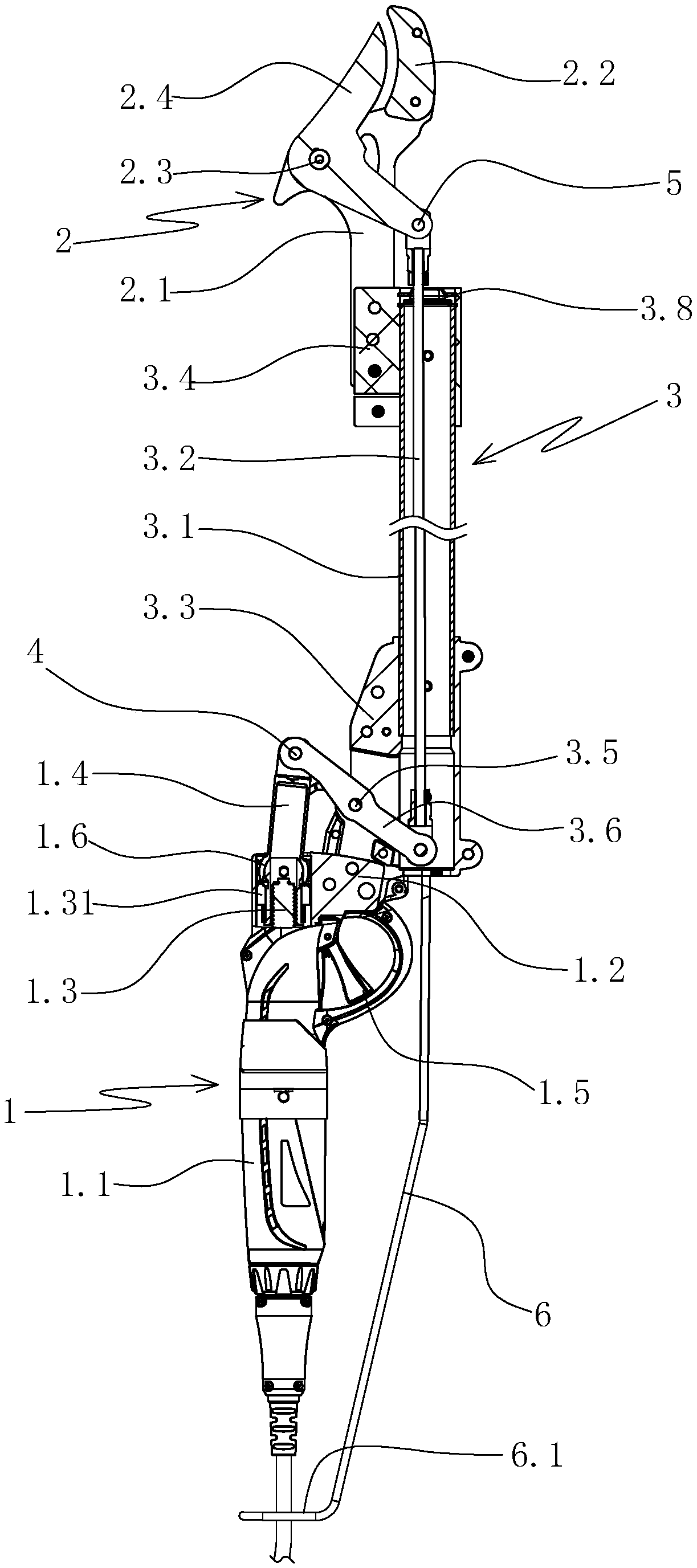
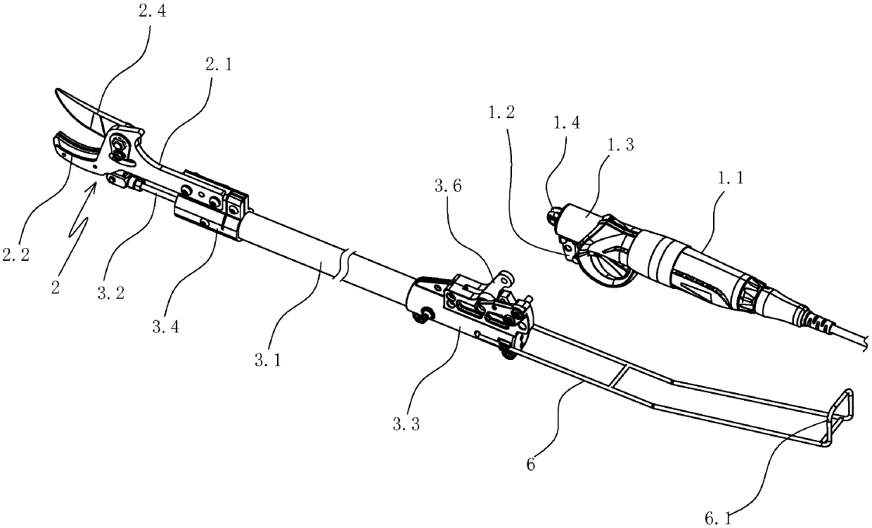
[0037] Specific embodiment one: as figure 1 , figure 2 , image 3 As shown, an electric high branch shear includes a scissors main body 1 , a scissors assembly 2 and a high branch assembly 3 . The scissors main body 1 includes a housing 1.1, a housing mounting portion 1.2 disposed on the housing, an electric push rod 1.3 and a push rod 1.4 disposed on the housing. The end of the push rod 1.31 of the electric push rod is hingedly connected to the first end of the ejector rod or connected through a ball joint. In this embodiment, the end of the push rod 1.31 of the electric push rod is connected to the first end of the ejector rod through Ball joint 1.6 connection.

[0038] The scissors assembly 2 includes a scissors installation part 2.1, a fixed blade 2.2 arranged on the scissors installation part, and a rotating blade 2.4 arranged on the scissors installation part through the rotation of the first pin shaft 2.3.

[0039] The high branch assembly 3 includes a high branch...

specific Embodiment 2

[0047] Specific embodiment two: the specific structure of this embodiment is with reference to specific embodiment one, and its difference is:

[0048] Such as Figure 5 As shown, an electric high branch shear also includes an auxiliary breaking device 7 . The auxiliary breaking device includes an auxiliary pipe 7.1 parallel to the high-branch pipe, a connector 7.2 connecting the auxiliary pipe and the high-branch pipe, an auxiliary rod 7.7 inserted in the auxiliary pipe, a mounting seat 7.3 arranged on the upper end of the auxiliary pipe, and a Mounting plate 7.4 and the breaking bar 7.6 that is arranged on the mounting plate by the 5th bearing pin 7.5 rotation. The breaking rod is L-shaped. The fifth pin shaft is coaxial or parallel to the first pin shaft, and the fifth pin shaft is located at the bending part of the broken rod. The lower end of the auxiliary rod passes through the lower end of the auxiliary pipe and is positioned at the outside of the auxiliary pipe. The...


PUM


Abstract

The invention discloses a pair of electrical high-branch shears, and aims at providing a pair of electrical high-branch shears that is convenient to use, rapid for pruning, and capable of realizing reliably pruning a relatively high branch. The pair of electrical high-branch shears comprises a shear body, a shear assembly and a high branch assembly, wherein the shear body comprises a casing, a casing installation part, an electrical push rod and an ejector rod, the casing installation part is arranged on the casing, and the electrical push rod and the ejector rod are arranged on the casing; the shear assembly comprises a shear installation part, a fixed shear blade and a rotary shear blade, the fixed shear blade is arranged on the shear installation part, and the rotary shear blade is rotationally arranged on the shear installation part; the high branch assembly comprises a high branch pipe, a pull rod, a connecting base, a fixing base and a reverse rod, the pull rod is inserted into the high branch pipe, the connecting base is arranged at the lower end of the high branch pipe, the fixing base is arranged at the upper end of the high branch pipe, the reverse rod is rotationally arranged on the connecting base, the connecting base is arranged on the casing installation part, one end of the reverse rod is connected with the second end of the ejector rod in a hinge way, and the other end of the reverse rod is connected with the lower end of the pull rod in a hinge way; the shear installation part is arranged on the fixing base, and the rotary shear blade is connected with theupper end of the pull rod in a hinge way.

Description

technical field [0001] The invention relates to a kind of pruning shears, in particular to an electric high branch shears. Background technique [0002] Pruning shears are a commonly used pruning tool at present. The current pruning shears are usually manual pruning shears. Although the structure is simple, the pruning is relatively laborious, especially for the pruning of taller branches, often with the help of long ladders. Climbing, inconvenient to use, and there is the problem of potential safety hazard; For this reason, some present inventors fix the pruning shears on the upper end of the high branch bar, so that the pruning personnel can stand on the ground by holding the lower end of the high branch bar for comparison. High branches are pruned, but the pruners need to manually operate the pruning shears fixed on the upper end of the high branches at the lower end of the high branches to achieve pruning. Twig problem. [0003] On the other hand, the pruning shears on...

Claims


Application Information

Patent Timeline
Patent Type & Authority Applications(China)
IPC IPC(8): A01G3/033A01G3/037
CPCA01G3/0335A01G3/037
Inventor 应林奇徐森严
Owner ZHEJIANG DONGQIAO PRECISION MACHINERY CO LTD
Why Eureka
Try Eureka