Movable cable ditch dehumidifier

A cable trench and dehumidifier technology, applied in the directions of dispersed particle separation, chemical instruments and methods, separation methods, etc., can solve the problems of cable trench collapse, cable frame rust, cable damp, etc., to improve production efficiency, liberate labor, The effect of a large dehumidification range

Inactive Publication Date: 2019-04-23
HAIBEI POWER SUPPLY COMPANY STATE GRID QINGHAI ELECTRIC POWER +2
View PDF7 Cites 0 Cited by
  • Summary
  • Abstract
  • Description
  • Claims
  • Application Information

AI Technical Summary

Problems solved by technology

[0002] The water in the cable trench is damp, which will cause problems such as cable damp, cable frame rust and cable trench collapse for a long time
Seriously affect the service life of cables and cable trenches
The problem of cable trench dehumidification has been plagued by various power supply companies. At present, all companies use the method of installing vents and opening the cable trench cover to dry in the sun to reduce the problem of cable trench moisture. This method, due to the lack of air circulation inside the cable trench, can only The cable groove about one meter on both sides of the cable cover plate can dehumidify, but it cannot dehumidify the cable groove as a whole, and the efficiency is low

Method used


Image

  • Movable cable ditch dehumidifier
  • Movable cable ditch dehumidifier
  • Movable cable ditch dehumidifier

Examples


Embodiment 1

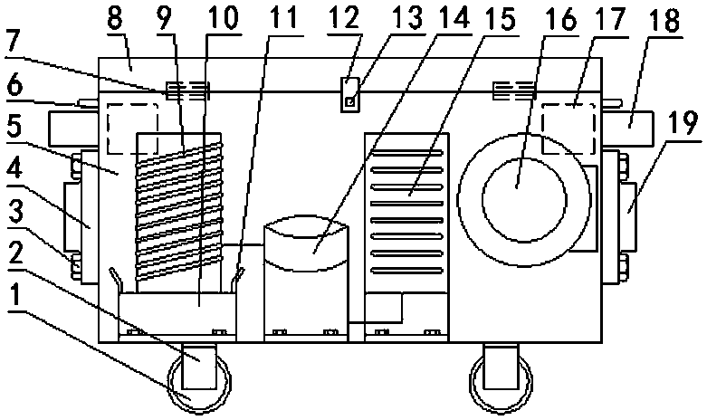
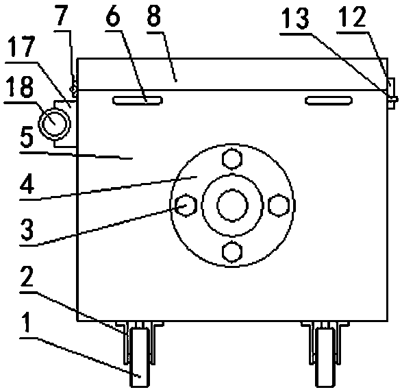
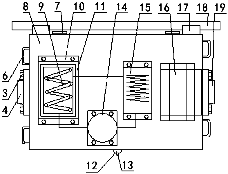
[0011] Embodiment 1: A movable cable ditch dehumidifier, which consists of a box (5), a box cover (8), an evaporator (9), a water tank (10), a compressor (14), and a condenser (15) , blower fan (16), air duct sleeve (18), air duct (20), and air duct joint (22). Fasten through buckle A (11) and buckle B (12), there is a sealing strip at the joint, and the front and rear ends of the box (5) are respectively fixed with the air inlet pipe interface (4) and the air outlet pipe interface by bolts (3) (19), an evaporator (9), a water tank (10), a compressor (14), a condenser (15), and a fan (16) are fixed inside the box body (5), wherein the evaporator (9), the compressor (14) and the condenser (15) are connected by pipes, the evaporator (9) is fixed on the water tank (10), and the upper edge of the water tank (10) is provided with a flanging (11) to form a water tray, the water tank The top of (10) has some small holes, and water tank (10) is fixed on the bottom of casing (5), and ...


PUM


Abstract

The invention discloses a movable cable ditch dehumidifier, and relates to the technical field of cable ditch dehumidifying. The structure of the movable cable ditch dehumidifier is that the back surface of a box body is hinged to a box cover through hinges; the front surface of the box body is buckled with the box cover through a hasp A and a hasp B; the front end and the rear end of the box bodyare respectively fixed with an air inlet pipe connector and an air outlet pipe connector through bolts; an evaporator, a water tank, a compressor, a condenser and a fan are fixedly arranged in the box body, wherein the evaporator, the compressor and the condenser are connected with one another through pipelines; a plurality of small holes are formed in the top of the water tank; and an air outletof the fan is connected with the air outlet connector. The movable cable ditch dehumidifier has the beneficial effects that a dehumidifying effect is achieved on the interior of a cable ditch by circulating the processes of sucking wet air in the cable ditch into the dehumidifier through an air inlet pipe, removing water and drying, and feeding dry air into the cable ditch through an air outlet pipe by utilizing the air conditioner dehumidifying principle, so that the labour force is liberated; the production efficiency is improved; the operation is convenient; the space is not occupied; thedehumidifying range is range; and the requirements on dehumidifying the cable ditch in different areas can be met.

Description

technical field [0001] The invention relates to the technical field of cable trench dehumidification, in particular to a movable cable trench dehumidifier. Background technique [0002] The accumulated water in the cable trench is damp, which will cause problems such as cable damp, cable frame rust and cable trench collapse for a long time. Seriously affect the service life of cables and cable trenches. The problem of cable trench dehumidification has been plagued by various power supply companies. At present, all companies use the method of installing vents and opening the cable trench cover to dry in the sun to reduce the problem of cable trench moisture. This method, due to the lack of air circulation inside the cable trench, can only The cable trench about one meter on both sides of the cable cover plate can dehumidify, but it cannot dehumidify the cable trench as a whole, and the efficiency is low. Contents of the invention [0003] Aiming at the problems existing i...

Claims


Application Information

Patent Timeline
Patent Type & Authority Applications(China)
IPC IPC(8): B01D53/26
CPCB01D53/26
Inventor 王一博张志刚庞伟生李小晖郑永燕刘士峰史建成刘小凡李振兴刘世超郑麟苏伟王科魏鸿福葛冠超
Owner HAIBEI POWER SUPPLY COMPANY STATE GRID QINGHAI ELECTRIC POWER
Why Eureka
Try Eureka