A hot box structure of a coating machine for producing antibacterial and deodorizing nylon

A technology of coating machine and odorous nylon, which is applied in the field of hot box structure of the coating machine for producing antibacterial and deodorizing nylon, which can solve the problems of uneven heating of silk speed, slippage, automatic regulation of no set temperature, etc., to achieve uniformity Sexuality, avoid slippage, improve the effect of the range of use

Active Publication Date: 2020-12-15
ZHEJIANG LONGSTAR TECH CO LTD
View PDF13 Cites 0 Cited by
  • Summary
  • Abstract
  • Description
  • Claims
  • Application Information

AI Technical Summary

Problems solved by technology

[0003] The purpose of the present invention is to provide a hot box structure for coating machine for producing antibacterial and deodorizing nylon, so as to solve the problem of uneven heating of the wire speed by the hot box structure proposed in the above background technology, no automatic temperature control and high speed running of the wire speed prone to slippage

Method used


Image

  • A hot box structure of a coating machine for producing antibacterial and deodorizing nylon
  • A hot box structure of a coating machine for producing antibacterial and deodorizing nylon
  • A hot box structure of a coating machine for producing antibacterial and deodorizing nylon

Examples


Embodiment Construction

[0018] The following will clearly and completely describe the technical solutions in the embodiments of the present invention with reference to the accompanying drawings in the embodiments of the present invention. Obviously, the described embodiments are only some, not all, embodiments of the present invention. Based on the embodiments of the present invention, all other embodiments obtained by persons of ordinary skill in the art without making creative efforts belong to the protection scope of the present invention.

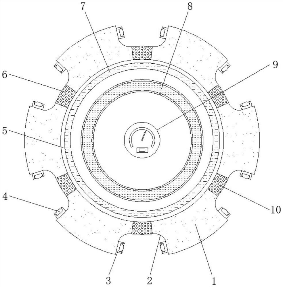
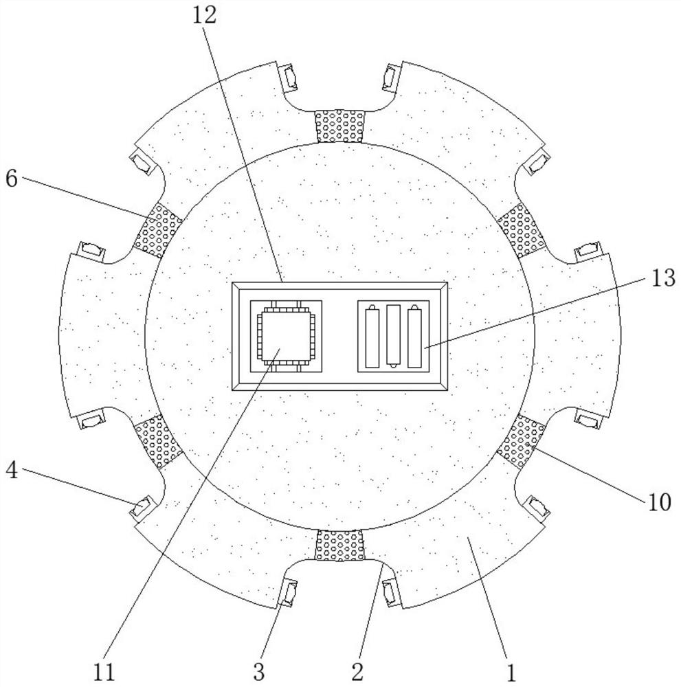
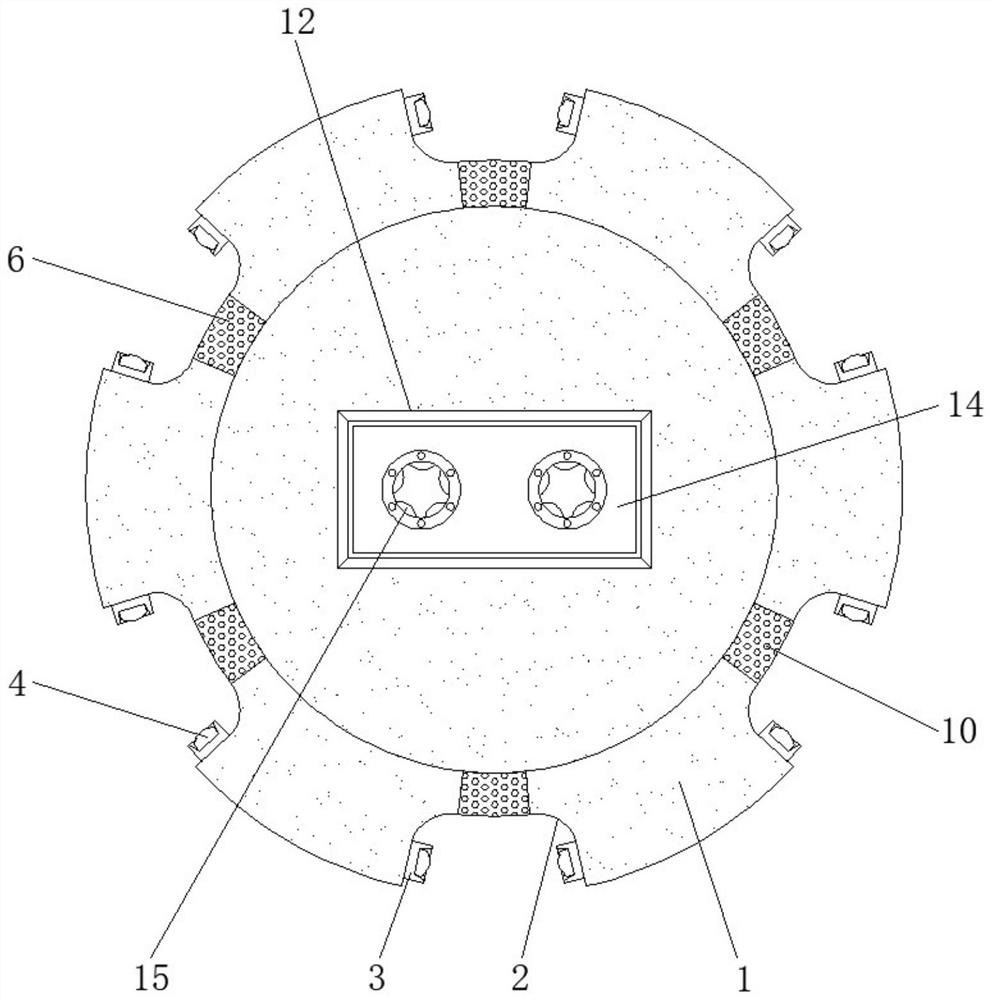
[0019] see Figure 1-3 , an embodiment provided by the present invention: a hot box structure of a coating machine for producing antibacterial and deodorizing nylon, including a hot box body 1, a hot box silk channel 2, a wire retaining frame 3, an electric heating ring 8 and an alarm device 15, six groups of hot box silk paths 2 are arranged at the edge of the hot box body 1, and the included angle between adjacent hot box silk paths 2 is 60 degrees, and the ...


PUM


Abstract

The invention discloses a cladding machine heat box structure for producing bacteriostasis deodorization chinlon. The cladding machine heat box structure comprises a heat box body, heat box silk channels, yarn stop frames, an electric heating ring and alarm devices. The six heat box silk channels are formed in the edge of the heat box body, and the included angle between every two adjacent heat box silk channels is 60 degrees. The two ends of the inner side walls of the heat box silk channels are each provided with the corresponding yarn stop frame. A distance sensor is mounted in the center of the side, away from the heat box body, of each yarn stop frame. A treatment frame is fixed to the center of the outer side wall of the heat box body. A single chip microcomputer is mounted at one end inside the treatment frame. An accumulator is fixed to the position, at one side of the single chip microcomputer, inside the treatment frame. A cover plate is mounted at the position, at one side of the accumulator, of the side wall of the treatment frame. A heat box inner chamber is formed in the center inside the heat box body. A temperature detector is mounted inside the heat box inner chamber. By means of the cladding machine heat box structure, the uniformity of silk bundle heating conducted through the heat box structure is improved, the function of automatically adjusting the internal temperature of a heat box is achieved, and the phenomenon that a silk bundle slips off in the high-speed moving process is avoided.

Description

technical field [0001] The invention relates to the technical field of coating machines, in particular to a hot box structure of a coating machine for producing antibacterial and deodorizing nylon. Background technique [0002] With the development of industrial economy, industrial mechanization and intelligence are gradually deepening. In the textile field, many spun yarns need to be rolled into rolls, and this requires special machinery to complete, so there is Yarn covering machine, while the traditional yarn covering machine is relatively bulky, the structure is relatively complicated, and it is inconvenient to move. Trouble, this technical scheme enables the yarn covering machine to distribute the yarn on the reel more evenly when winding the yarn, and can automatically unload the material, saving manpower. Among them, the modified heating box is an important part of the coating machine. When the tow travels at a high speed in the modified heating box, the contact surf...

Claims


Application Information

Patent Timeline
Patent Type & Authority Patents(China)
IPC IPC(8): B65H54/70B65H63/00
CPCB65H54/70B65H63/00B65H2701/31
Inventor 沈建炳
Owner ZHEJIANG LONGSTAR TECH CO LTD
Why Eureka
Try Eureka