Cleaning device of lens of camera

A technology for cleaning equipment and cameras, which is applied to cleaning methods using liquids, cleaning methods and utensils, chemical instruments and methods, etc., and can solve the problem that there is no automatic control function, the cleaning equipment is not equipped with water recovery and treatment functions, and the cleaning equipment cannot be realized. Lens cleaning function and other issues to achieve the effect of improving the scope of application and realizing the automatic adjustment function

Inactive Publication Date: 2019-01-15
JIANGSU TONGSHENG PHOTOELECTRIC TECH CO LTD
View PDF0 Cites 0 Cited by
  • Summary
  • Abstract
  • Description
  • Claims
  • Application Information

AI Technical Summary

Problems solved by technology

In modern social life, there are many devices that can record images. They all have the characteristics of a camera, such as medical imaging equipment, astronomical observation equipment, etc. Usually, the main components of a camera include: imaging components, darkrooms, imaging media and imaging control structures, and The imaging element is usually a lens group made of optical glass, which is called a lens. However, the main part of the lens is the lens. However, cleaning is often required during the processing of the lens, which requires the use of cleaning equipment. The current cleaning The equipment is not equipped with the function of recycling water quality, and some cleaning equipment is not equipped with the function of automatic regulation of water temperature during use, and even some cleaning equipment cannot realize the cleaning function of different lenses

Method used


Image

  • Cleaning device of lens of camera
  • Cleaning device of lens of camera
  • Cleaning device of lens of camera

Examples


Embodiment Construction

[0014] The following will clearly and completely describe the technical solutions in the embodiments of the present invention with reference to the accompanying drawings in the embodiments of the present invention. Obviously, the described embodiments are only some, not all, embodiments of the present invention. Based on the embodiments of the present invention, all other embodiments obtained by persons of ordinary skill in the art without making creative efforts belong to the protection scope of the present invention.

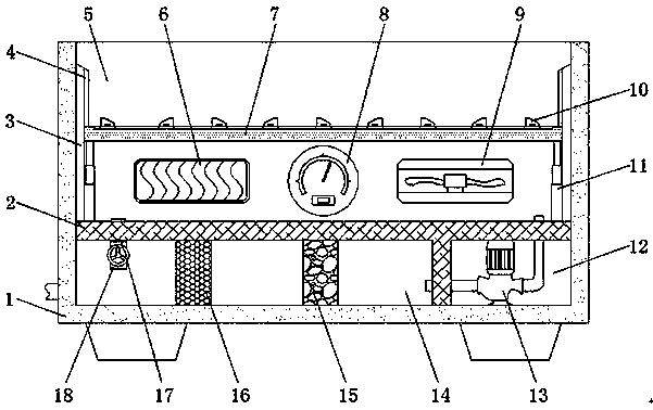
[0015] see Figure 1-3 , an embodiment provided by the present invention: a cleaning device for camera lenses, including a device main body 1, a partition plate 2, a sliding frame 3, a support block 10 and an activated carbon layer 15, and the bottom end of the device main body 1 is provided with a partition Board 2, the inside of the main body 1 of the equipment below the partition 2 is provided with a recovery chamber 14, and the interior of the partition 2 ...


PUM


Abstract

The invention discloses a cleaning device of a lens of a camera. The cleaning device of the lens of the camera comprises a device body, a partition plate, a sliding frame, supporting blocks and an activated carbon layer. The partition plate is arranged at the bottom end of the inner portion of the device body. A recycling chamber is arranged in the device body and located below the partition plate. A water conveying pipeline is arranged in the portion, located at the recycling chamber, of the partition plate. A filtering net is fixed to one side of the inner portion of the recycling chamber. The activated layer is installed in the recycling chamber and located on one side of the filtering net. A storage chamber is arranged in the device boy and located on one side of the recycling chamber.A water pump is installed at the center of the inner portion of the storage chamber. A cleaning chamber is arranged in the device body and located above the partition plate. The two sides of the topend of the cleaning frame are both provided with sliding grooves. A control panel is fixed to the center of the outer side wall of the device body. The cleaning device of the lens of the camera expands the application range of the cleaning device, achieves the automatic adjustment and control function of the water temperature of the cleaning device and achieves the energy-saving and environmentalprotection purposes.

Description

technical field [0001] The invention relates to the technical field of cleaning equipment, in particular to a cleaning equipment for camera lenses. Background technique [0002] A camera is a device that uses the principle of optical imaging to form an image and uses a film to record the image. It is an optical device used for photography. In modern social life, there are many devices that can record images. They all have the characteristics of a camera, such as medical imaging equipment, astronomical observation equipment, etc. Usually, the main components of a camera include: imaging components, darkrooms, imaging media and imaging control structures, and The imaging element is usually a lens group made of optical glass, which is called a lens. However, the main part of the lens is the lens. However, cleaning is often required during the processing of the lens, which requires the use of cleaning equipment. The current cleaning The equipment is not equipped with the functi...

Claims


Application Information

Patent Timeline
Patent Type & Authority Applications(China)
IPC IPC(8): B08B3/10B08B3/14B08B13/00
CPCB08B3/044B08B3/14B08B13/00
Inventor 何同军汪渊
Owner JIANGSU TONGSHENG PHOTOELECTRIC TECH CO LTD
Why Eureka
Try Eureka