Regulation valve cavitation diagnosis system and method

A technology of diagnosis system and diagnosis method, applied in the direction of mechanical valve testing, mechanical component testing, machine/structural component testing, etc., can solve the problem of no more research on cavitation detection and diagnosis.

Active Publication Date: 2019-04-23
ZHEJIANG UNIV OF TECH
View PDF14 Cites 7 Cited by
  • Summary
  • Abstract
  • Description
  • Claims
  • Application Information

AI Technical Summary

Problems solved by technology

[0005] At present, there is no more research on the detection and diagnosis of cavitation in China, but cavitation evaluation of control valves is required under many working conditions

Method used


Image

  • Regulation valve cavitation diagnosis system and method
  • Regulation valve cavitation diagnosis system and method
  • Regulation valve cavitation diagnosis system and method

Examples


Embodiment Construction

[0031] Hereinafter, embodiments of the present invention will be described with reference to the drawings.

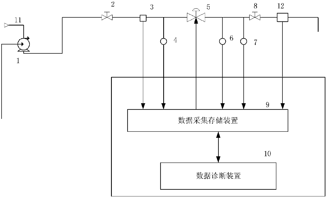
[0032] figure 1 It is a structural schematic diagram of the cavitation diagnosis system of the regulating valve of the present invention. It can be seen from the figure that the diagnostic system of the present invention mainly includes four parts: diagnostic regulating valve test pipeline device, signal measurement device, data acquisition and storage device, and data diagnosis device 10; of which:

[0033] The diagnostic regulating valve test pipeline device is used to provide a pressurized flow environment for diagnosing the regulating valve to be tested. 5. Throttle valve 8 after the valve and the connecting pipeline passage between them. The multistage centrifugal pump 1 is connected with a multistage centrifugal pump frequency converter 11. The multistage centrifugal pump 1 is used to provide relative pressure. The multistage centrifugal pump The frequency conve...


PUM


Abstract

The invention relates to a regulation valve cavitation diagnosis system and method. A regulation valve testing pipeline system comprises a multistage centrifugal pump, a multistage centrifugal pump frequency changer, a to-be-tested regulation valve of a diagnosed object, an upstream stop valve, a downstream throttle valve and a system pipeline to be tested, wherein the multistage centrifugal pumpis used for providing relative pressure; the multistage centrifugal pump frequency changer is used for regulating the revolving speed of the multistage centrifugal pump; and the upstream stop valve and the downstream throttle valve are respectively arranged in front of and behind the to-be-tested regulation valve. According to the invention, through adopting the above technology, upstream pressurein front of the to-be-tested regulation valve, downstream pressure behind the to-be-tested regulation valve, Z-axis vibration acceleration behind the to-be-tested regulation valve and flow in front of the to-be-tested regulation valve are utilized for calculating and judging whether cavitation happens or not; through a cavitation diagnosis device, the cavitation parameters of the regulation valveunder a certain aperture are diagnosed, so that a condition for cavitation under a current regulation valve aperture can be accurately obtained, and the effectiveness value of the vibration acceleration, working condition parameters, cavitation parameters and cavitation severity coefficients can be solved, so that the cavitation diagnosis evaluation of the regulation valve is realized.

Description

technical field [0001] The invention relates to a control valve cavitation diagnosis system and a diagnosis method thereof. Background technique [0002] As an important executive component in the process control system, the regulating valve is a key concern whether it operates safely, stably and reliably. Among them, cavitation is a common phenomenon in the control valve. [0003] Cavitation is divided into two processes, namely flashing and cavitation: flashing is when the incompressible fluid flows through the regulating valve, the static pressure from the contraction section to the valve outlet is reduced to be equal to or lower than the temperature of the fluid at the valve inlet When the saturated vapor pressure is lower, part of the liquid vaporizes to form a vapor-liquid two-phase phenomenon behind the valve; cavitation is when the incompressible fluid flows through the regulating valve, the static pressure from the contracted flow section to the valve outlet decrea...

Claims


Application Information

Patent Timeline
Patent Type & Authority Applications(China)
IPC IPC(8): G01M13/003G01N3/56G01N3/02
CPCG01M13/00G01N3/02G01N3/567
Inventor 尚群立俞轲鑫陈永皓王劲松吕杨康庞仁贵
Owner ZHEJIANG UNIV OF TECH
Why Eureka
Try Eureka