Portable charger

A portable charger and charging cable technology, which is applied in current collectors, electric vehicles, electrical components, etc., can solve the problems of charger movement, loose charging cables, and large charging distances, and improve the convenience of retracting and charging. ,Easy to carry and move

Inactive Publication Date: 2019-04-23
泉州瑞思蚂蚁电子商务有限公司
View PDF0 Cites 0 Cited by
  • Summary
  • Abstract
  • Description
  • Claims
  • Application Information

AI Technical Summary

Problems solved by technology

[0003] However, the current existing chargers are often connected to the electrical appliance and the power supply through the charging cable when in use. The charging distance depends on the length of the charging cable. The longer the length, the greater the charging distance. It is very inconvenient to store the charger due to the loose charging cable during the process of carrying and moving, and even if the charging cable is rolled up, it will still be loose

Method used


Image

  • Portable charger
  • Portable charger
  • Portable charger

Examples


Embodiment 1

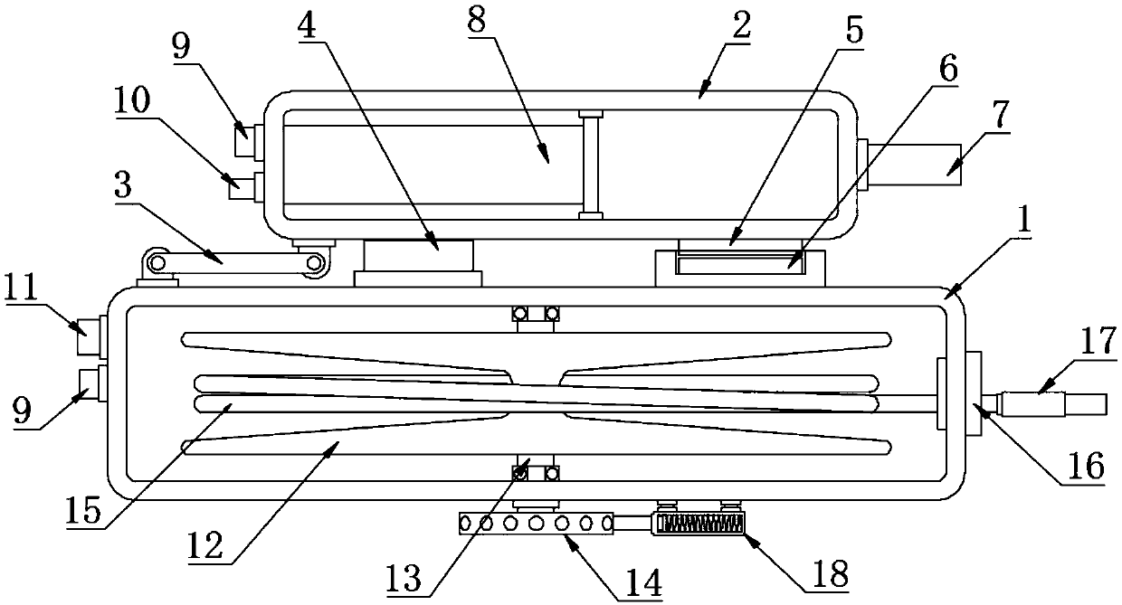
[0020] see Figure 1~3 , in an embodiment of the present invention, a portable charger includes a winding box 1, an adapter 2, a wire roller 12 and a locking device 18; the adapter 2 is hinged on the top of the winding box 1 through a connecting rod 3, wherein the winding A rubber pad 4 is fixed on the upper surface of the box 1. The upper surface of the rubber pad 4 is attached to the lower surface of the adapter 2, and the lower surface of the adapter 2 is fixed on the side opposite to the rubber pad 4. The first magnetic block 5 is fixed below the first magnetic block 5. Two magnetic blocks 6, the second magnetic block 6 is fixed on the upper surface of the winding box 1, it should be noted that the opposite sides of the first magnetic block 5 and the second magnetic block 6 are opposite magnetic poles, and the adapter 2 hinged by the connecting rod 3 And the winding box 1 can be flipped and folded, which is convenient for storage and carrying. The rubber pad 4 is used to s...

Embodiment 2

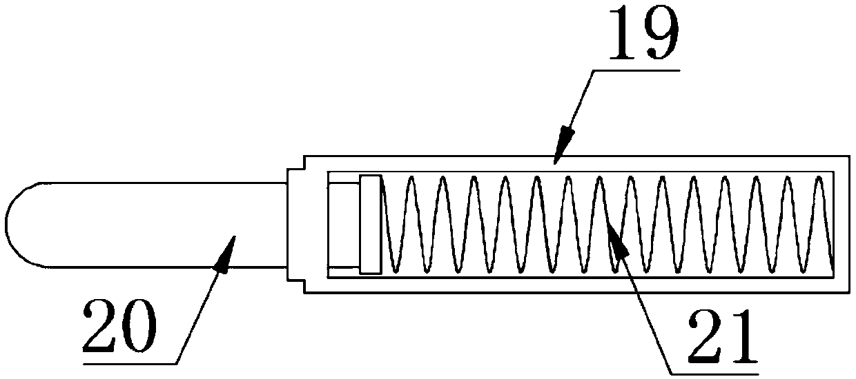
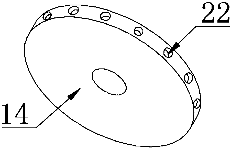
[0023] In order to make the technical solutions in this application more detailed and complete, now some supplements and explanations are made on the basis of the above-mentioned embodiment 1, so that the disclosure of the technical means adopted in this application is more sufficient, specifically, the supplements and explanations Part of the technical feature is that the locking device 18 includes a ferrule 19, an insertion rod 20 and a spring 21, wherein the ferrule 19 is fixed on the outer surface of the winding box 1, and the ferrule 19 is slidably connected with the insertion rod 20, and the insertion rod 20 is inserted One end of the rod 20 abuts against the lock hole 22, the other end of the insertion rod 20 is connected to the end of the spring 21, and the other end of the spring 21 fixes the inner bottom of the ferrule 19. In order to increase the locking force, the spring 21 is always in a compressed state. The elastic force of the spring 21 drives the insertion rod ...


PUM


Abstract

The invention discloses a portable charger, and relates to power equipment, which solves the problems that a charging wire in an existing charger is not easy to store and inconvenient to carry. According to the specific design thought of the invention, the overturning and the folding of the portable charger can be realized through an adapter and a winding box which are hinged through a connectingrod. The portable charger is convenient to fold, unfold and carry about. A first magnetic block and a second magnetic block attract each other to realize the fixation purpose when the adapter and thewinding box are folded. When the charging is needed, the adapter is switched on rotationally. In this way, the first magnetic block and the second magnetic block are separated. Meanwhile, the adapterand the winding box are kept on the same horizontal plane. At the moment, the adapter abuts against the winding box by means of embedded blocks, wherein a male block is inserted into a female block torealize the electric connection. A rotating wheel is rotated to drive a rotating shaft to rotate so as to drive a wire roller to rotate, so that a charging wire wound on the surface of the wire roller is wound up or unwound. As a result, the charging wire is stored. The rotating wheel is fixed through a locking device, and the charging wire is prevented from being automatically loosened under theaction of the external force or gravity in the charging or carrying process.

Description

technical field [0001] The invention relates to a power device, in particular to a portable charger. Background technique [0002] With the continuous development of technology, many new technologies and concepts in the field of computers and power electronics have been introduced into the charging industry. Compared with the previous products, the charger has made significant progress in terms of main performance, appearance size, adaptability to the field environment and reliability. Some indicators even have a qualitative leap. For large and medium-sized chargers Even more so. [0003] However, the current existing chargers are often connected to the electrical appliance and the power supply through the charging cable when in use. The charging distance depends on the length of the charging cable. The longer the length, the greater the charging distance. The problem is that the charger is very inconvenient to store due to the loose charging cable during the process of ca...

Claims


Application Information

Patent Timeline
Patent Type & Authority Applications(China)
IPC IPC(8): H02J7/00H02G11/02
CPCH02J7/0045H02G11/02
Inventor 李靖黄剑峰
Owner 泉州瑞思蚂蚁电子商务有限公司
Why Eureka
Try Eureka