
Internet of Things storage cabinet

A technology of lockers and the Internet of Things, applied in the field of lockers, can solve the problems of not being able to find designated items, chaotic management of cabinets, and low monitoring efforts

Inactive Publication Date: 2019-04-26
HARBIN NORMAL UNIVERSITY
View PDF14 Cites 1 Cited by
  • Summary
  • Abstract
  • Description
  • Claims
  • Application Information

AI Technical Summary

Problems solved by technology

Moreover, the existing large-scale cabinets have a low degree of intelligence, and it takes time to find the corresponding items in the cabinet; and when returning the tools, the monitoring is low, and it is easy to return and misplace the phenomenon, which leads to confusion in the management of the entire cabinet. The corresponding designated items cannot be found in the corresponding place; and the current large cabinets are located on the indoor ground, so that the surveillance cameras have monitoring dead spots, which can only be avoided by installing multiple cameras at various angles
Therefore, the existing large cabinets are no longer suitable for specific occasions

Method used


Image

  • Internet of Things storage cabinet
  • Internet of Things storage cabinet
  • Internet of Things storage cabinet

Examples


Embodiment 1

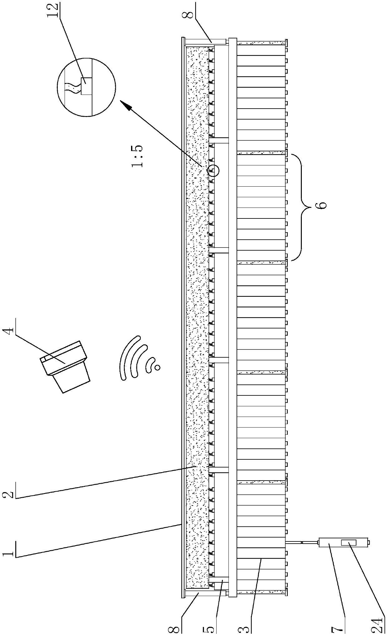
[0023] The present invention is an Internet of Things locker, the main structure includes a beam 1, a system box 2, a cabinet body 3, a box lifting device and an external data control terminal 4; the beam 1 is connected to the top plate of the cabinet body 3, and the The system box 2 is fixed on the top board of the cabinet body 3 through the support column 5, and the top board is fixed on the top ceiling of the storage room. The whole device is fixedly arranged in the storage room according to the above method, and it is located at the top of the storage room, so that all the bottom space of the storage room can be saved for other purposes, so that the entire storage room interior space can be reasonably utilized.

[0024] Described cabinet body 3 comprises a plurality of mutually independent large cabinet boxes 6, and described large cabinet box 6 comprises a plurality of mutually independent small cabinet boxes 7, stores articles in the small cabinet boxes 7, and each small ...

Embodiment 2

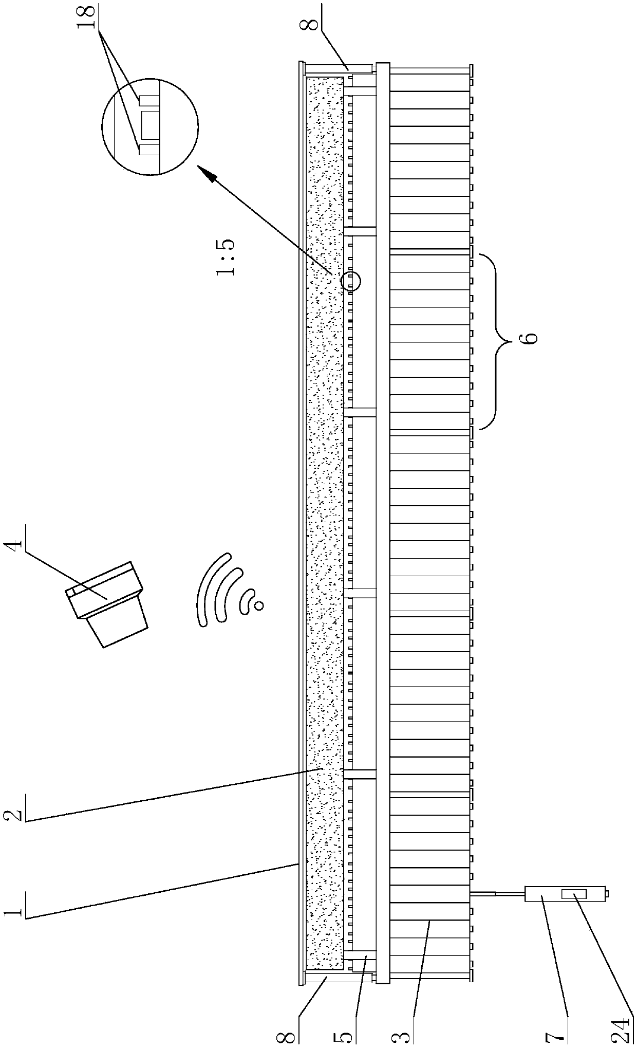
[0032] Compared with Embodiment 1, in Embodiment 2, the box body lifting device is a lifting device controlled by a rope body, and the lifting device controlled by the rope body is located in the device box at the top of the top plate of the cabinet body 3, and in the middle of the bottom plate of the device box The position is provided with limit rope hole 16, and the middle position of the top plate of described small cabinet box 7 top is provided with rope ring 17; And traction rope 21, the first section bar 22 of described space-limiting expansion link 18 is arranged on the both sides of cabinet body 3 top plate tops, and the last section bar 23 of described space-limiting expansion link 18 is arranged on the top plate of small cabinet box 7 tops On both sides, the rope winding servo motor 19 is arranged at the middle position of the top plate of the cabinet body 3, the rope winding wheel 20 is arranged at the output end of the rope winding servo motor 19, and the top end o...


PUM


Abstract

The invention discloses an Internet of Things storage cabinet, mainly relates to a cabinet. The Internet of Things storage cabinet comprises a crossbeam, a system tank, a cabinet body, box body lifting devices and an external data control terminal, wherein the cabinet body comprises a plurality of mutually independent small cabinet boxes, and each small cabinet box corresponds to one independent box body lifting device; a PLC execution terminal is arranged in the system tank and is used for controlling the box body lifting devices to correspondingly move according to a transmitted execution signal after a control signal is transmitted to the PLC execution terminal by the external data control terminal. The Internet of Things storage cabinet has the beneficial effects that the automatic fetching and returning of objects can be realized, and the effective monitoring can be well realizing during the fetching and returning of the objects, so that the phenomena that the management is disordered due to mistaken returning and misplacement, and an appointed object cannot be found in the corresponding place are avoided.

Description

technical field [0001] The invention relates to a cabinet, in particular to a locker that does not occupy indoor bottom space and is automatically controlled based on the Internet of Things. Background technique [0002] Existing lockers all are located on the indoor ground and are arranged in a manner of a plurality of cabinets arranged side by side. Corridors are to be set between adjacent cabinets to facilitate access to articles in the cabinets. Moreover, the existing large-scale cabinets have a low degree of intelligence, and it takes time to find the corresponding items in the cabinet; and when returning the tools, the monitoring is low, and it is easy to return and misplace the phenomenon, which leads to confusion in the management of the entire cabinet. The corresponding designated items cannot be found in the corresponding places; moreover, the large cabinets are located on the indoor ground, so that the surveillance cameras have monitoring dead spots, which can onl...

Claims


Application Information

Patent Timeline
Patent Type & Authority Applications(China)
IPC IPC(8): A47B81/00A47B53/00A47B51/00A47B95/00B66F7/06B66D1/74G07C9/00
CPCA47B51/00A47B53/00A47B81/00A47B95/00A47B95/008A47B2051/005A47B2220/0097B66D1/7447B66F7/0616B66F7/0666G07C9/00174
Inventor 姜春茂徐晓霞王松磊
Owner HARBIN NORMAL UNIVERSITY
Features
  • Generate Ideas
  • Intellectual Property
  • Life Sciences
  • Materials
  • Tech Scout
  • Unparalleled Data Quality
  • Higher Quality Content
  • 60% Fewer Hallucinations
Learn More