Wall surface spraying apparatus

A technology of spraying device and paint box, which is applied in the direction of construction and building construction, and can solve the problems of low efficiency, small spraying area, uneven spraying, etc., and achieve the effect of high spraying efficiency, uniform discharge, and good spraying quality

Inactive Publication Date: 2019-04-26
临海市天马装璜材料厂
View PDF7 Cites 3 Cited by
  • Summary
  • Abstract
  • Description
  • Claims
  • Application Information

AI Technical Summary

Problems solved by technology

However, this automatic spraying machine has small sprayi

Method used


Image

  • Wall surface spraying apparatus
  • Wall surface spraying apparatus
  • Wall surface spraying apparatus

Examples


Example Embodiment

[0029] Embodiment one

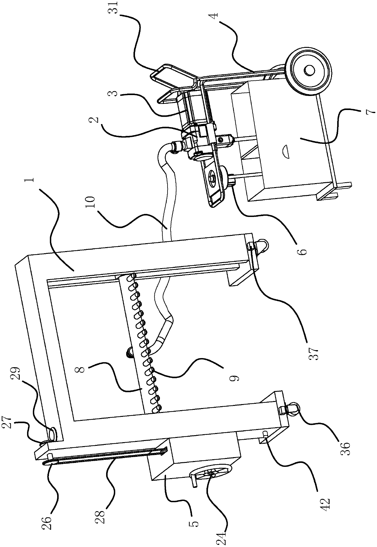
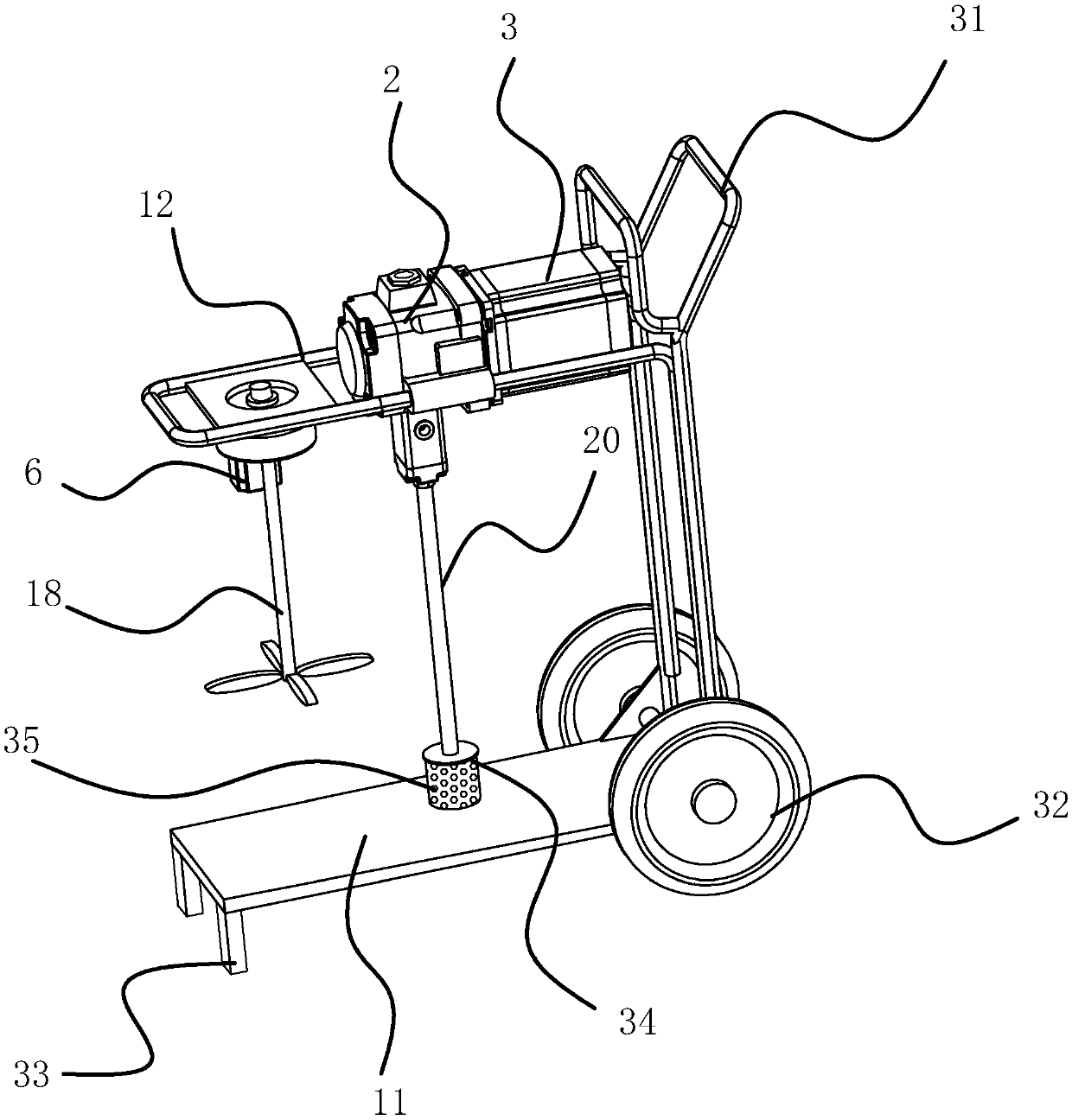
[0030] like Figure 1-4 As shown, the wall surface spraying device includes a gantry 1, a liquid pump 2, a water pump motor 3, a support trolley 4, a stirring motor 6, and a paint box 7. The gantry 1 is provided with a vertically lifting horizontal spraying tube 8, The hollow spraying horizontal pipe 8 has several spraying heads 9 arranged in a line along its length direction. The gantry 1 has a driving mechanism for driving the spraying horizontal pipe 8 up and down. The outlet of the pump 2 is connected to the spraying horizontal pipe 8. There is a feeding pipeline 10 connected between them, the support trolley 4 has a bottom plate 11 and an upper support frame 12, the liquid suction pump 2, the water pump motor 3 and the stirring motor 6 are fixed on the upper support frame 12, and the water pump motor 3 drives the liquid suction pump 2 to operate. The paint box 7 is placed on the base plate 11 of the support trolley 4, and the paint box 7 is divide...

Example Embodiment

[0039] Embodiment two

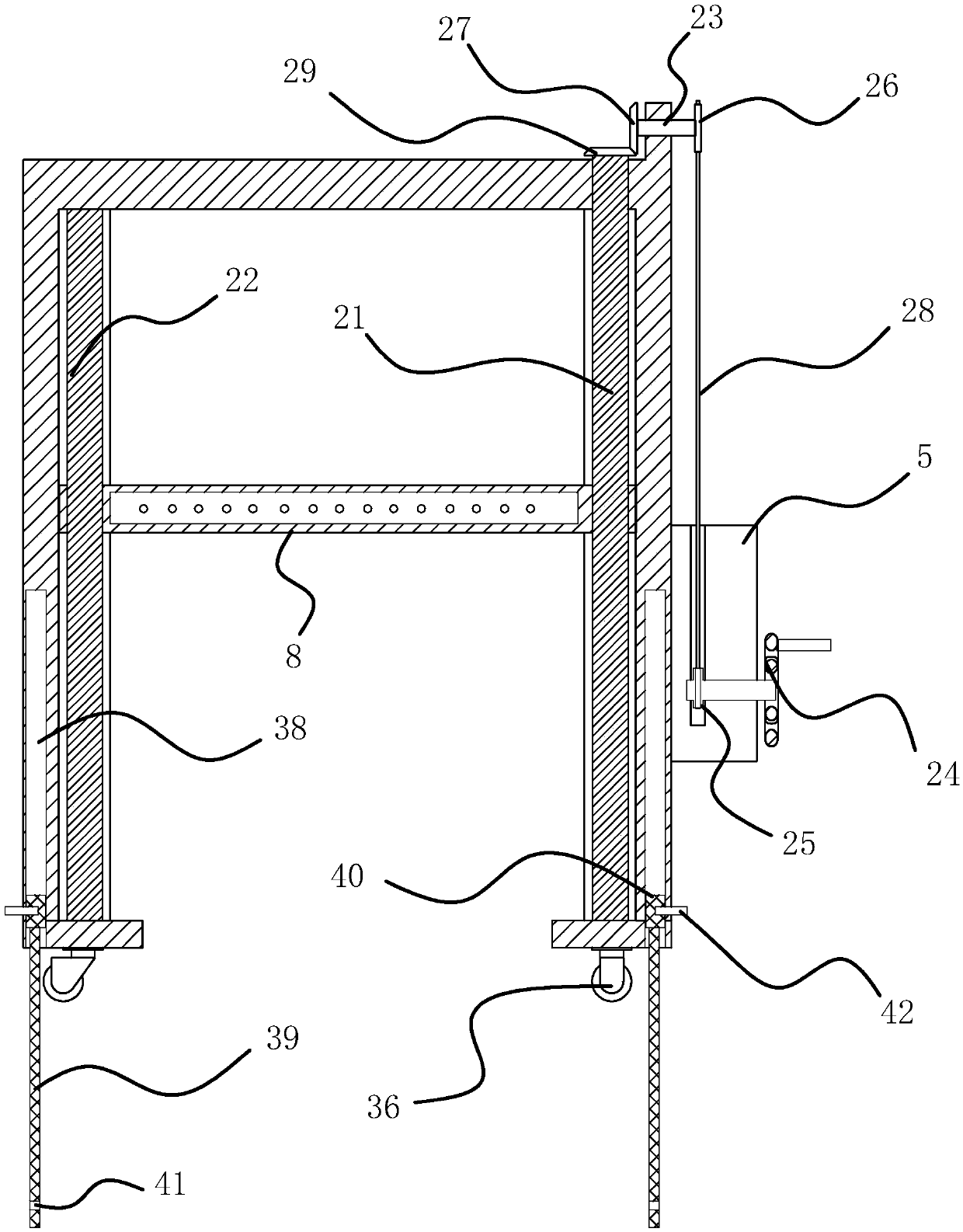
[0040] like Figure 5 As shown, the difference from Embodiment 1 is the drive mechanism. The drive mechanism of this embodiment includes a screw rod 21 and a guide rod 22 that are rotatably connected in the gantry 1, a transmission shaft 23 that is rotatably arranged on the top of the gantry 1, and a lifting motor 30. 1. The control box 5 that is connected to the side of the gantry frame 1, the lifting motor 30 is fixed in the control box 5, the output shaft of the lifting motor 30 is fixedly connected with the driving wheel 25, one end of the transmission shaft 23 is connected with the transmission wheel 26, and the other end is connected Helical gear one 27 is arranged, driving wheel 25 and driving wheel 26 are driven by belt 28, and the upper end of screw rod 21 passes through gantry frame 1 and is fixedly connected with helical gear two 29 meshing with helical gear one 27, and one end of spraying horizontal pipe 8 is screwed on On the screw rod 21 ...


PUM


Abstract

The invention provides a wall surface spraying apparatus. The wall surface spraying apparatus comprises a portal frame, a liquid extraction pump, a water pump motor, a support trolley, a stirring motor and a paint box, wherein the portal frame is provided with a spraying transverse pipe rising and falling vertically; the spraying transverse pipe is provided with a spraying head; the portal frame is provided with a driving mechanism for driving the spraying transverse pipe to rise and fall; a feeding pipeline is connected between an outlet of the liquid extraction pump and the spraying transverse pipe; the support trolley is provided with a bottom plate and an upper supporting frame; the liquid extraction pump, the water pump motor and the stirring motor are fixed on the upper supporting frame; and the water pump motor drives the liquid extraction pump to operate, the paint box is arranged on the bottom plate of the support trolley, the paint box is divided by a partition plate into twocavities, i.e. a stirring cavity and a material preparation cavity, a liquid discharging pipe is arranged on the bottom of the stirring cavity, a liquid discharging valve is arranged on the liquid discharging pipe, the stirring motor is in power connection with a stirring shaft extending into the stirring cavity, and a liquid inlet of the liquid extraction pump is connected with a liquid suctionpipe extending into the material preparation cavity. The wall surface spraying apparatus provided by the invention has high spraying efficiency, and large-area spraying can be completed by moving thespraying transverse pipe once.

Description

technical field [0001] The invention belongs to the technical field of paint spraying equipment, and relates to a wall surface spraying device. Background technique [0002] Wall paint refers to the decoration and protection of the building wall, making the building wall beautiful and tidy, and at the same time protecting the building wall and prolonging its service life. According to the classification of building walls, wall coatings include two major parts: interior wall coatings and exterior wall coatings. [0003] Existing wall surface spraying machines such as the patent No. 201710829586.6 published by the Chinese patent are a kind of automatic spraying and rolling machine for wall surface construction of buildings, including trolleys, mechanical arms, mechanical arm drive mechanisms, hydraulic power units, spraying mechanisms and Roll-off mechanism. Compared with the prior art, the present invention is more stable during operation and will not fall over; and the mor...

Claims


Application Information

Patent Timeline
IPC IPC(8): E04F21/08
CPCE04F21/08
Inventor 马行标
Owner 临海市天马装璜材料厂
Why Eureka
Try Eureka