Installation structure for L-shaped feet-lock bolt

A technology for locking the anchor rod and installing structure, which is applied in the installation of anchor rod, mining equipment, earth-moving drilling, etc., can solve the problems of inability to weld, low efficiency, difficult operation, etc., and achieve the effect of not easy to damage and fail.

Active Publication Date: 2019-04-26
宁波交通工程咨询监理有限公司
View PDF11 Cites 4 Cited by
  • Summary
  • Abstract
  • Description
  • Claims
  • Application Information

AI Technical Summary

Problems solved by technology

However, the use of the above-mentioned L-shaped locking foot bolt also has its limitations. When drilling the bolt hole, when the strength in the surrounding rock layer is poor, there is a hole collapse, looseness, etc., it is necessary to re-drill the bolt hole. The installation direction of the
For example, when the installation direction of the L-shaped locking foot anchor rod 3 is figure 1 When the direction of the middle arrow is not parallel to the side panel 7 of the steel arch 2, the tail end 4 of the L-shaped locking foot bolt 3 will not be able to fit the surface of the steel arch 2 facing away from the surrounding rock, so Can't weld here
Therefore, the limitations are very obvious, and the bending of the bolt on site also has problems such as difficult operation and low efficiency due to site restrictions and other reasons.

Method used


Image

  • Installation structure for L-shaped feet-lock bolt
  • Installation structure for L-shaped feet-lock bolt
  • Installation structure for L-shaped feet-lock bolt

Examples


Embodiment

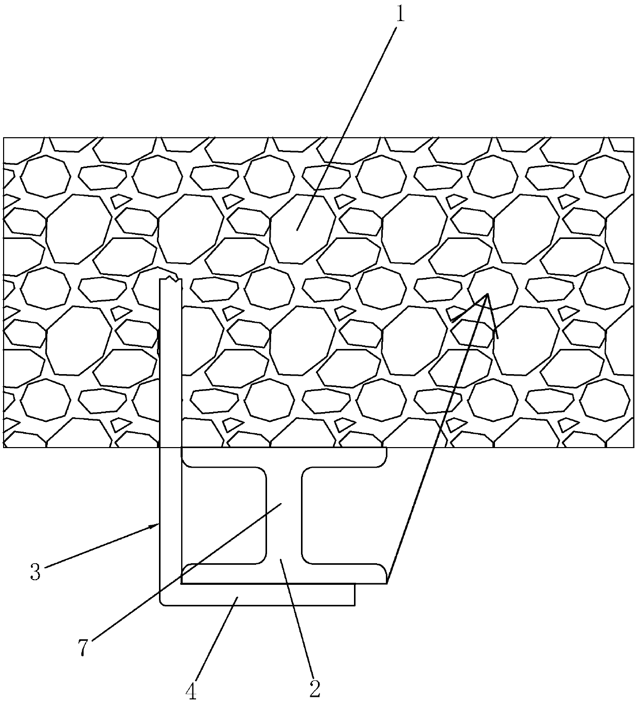
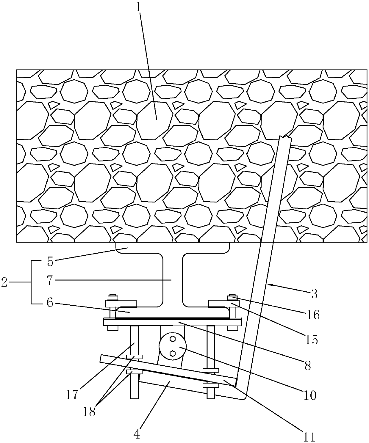
[0031] A kind of installation structure of L-shaped locking foot bolt, such as figure 2 As shown, it includes surrounding rock layer 1, steel arch frame 2, and L-shaped locking foot anchor rod 3; L-shaped locking foot anchor rod 3 includes a rod part and a tail end 4 perpendicular to the rod part; steel arch frame 2 adopts H-shaped steel Manufactured; the steel arch 2 includes an inner panel 5 facing the side of the surrounding rock layer 1, an outer panel 6 on the side away from the surrounding rock layer 1, and a side panel 7 connecting the inner panel 5 and the outer panel 6. The L-shaped locking foot bolt 3 is prefabricated in a factory and can be mass-produced.

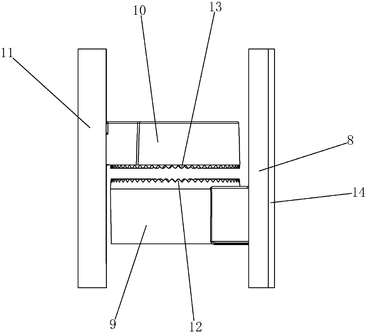
[0032] Such as Figure 2-3 As shown, it also includes a regulator of steel structure, the regulator includes a mounting plate 8, the mounting plate 8 is fixedly connected with the side of the steel arch 2 facing away from the surrounding rock layer 1, the mounting plate 8 is fixedly connected with a rotating se...


PUM


Abstract

The invention discloses an installation structure for an L-shaped feet-lock bolt. The installation structure comprises a surrounding rock stratum, a steel arch and the L-shaped feet-lock bolt, and further comprises a regulator; the L-shaped feet-lock bolt comprises a rod part and a tail end part perpendicular to the rod part; the regulator comprises a mounting plate, and the mounting plate is fixedly connected to the side, backing onto the surrounding rock stratum, of the steel arch; a rotating base is fixedly connected to the mounting plate; a circle of first meshing teeth are arranged in thecircumferential direction of the upper surface of the rotating base; a rotary base is connected to the rotating base, is provided with a circle of second meshing teeth engaging with the first meshingteeth and is connected to the rotating base through a bolt in a locked mode; a welding plate is fixedly connected to the rotary base; and the tail end part of the L-shaped feet-lock bolt is welded and fixed to the welding plate. The installation structure can be adaptable to installation of the L-shaped feet-lock bolt at different angles.

Description

technical field [0001] The invention relates to the technical field of tunnel construction, in particular to an installation structure of an L-shaped locking foot bolt. Background technique [0002] After the excavation of the tunnel chamber, the equilibrium state of the original surrounding rock is broken, and the surrounding surrounding rock and the vault produce plastic deformation and relaxation. In order to prevent the excessive displacement and deformation of the disturbed surrounding rock, reasonable support must be adopted. Protective structure to withstand the pressure of the surrounding rock. The steel arch frame is an important part of the initial support structure of tunnels with weak surrounding rocks, and it is also a part of the permanent support. Before, effectively control the deformation and displacement of the surrounding rock, bear the formation pressure and restrain the deformation. [0003] After the excavation of the tunnel, due to the release of the...

Claims


Application Information

Patent Timeline
Patent Type & Authority Applications(China)
IPC IPC(8): E21D21/00E21D20/00
CPCE21D20/00E21D21/0026
Inventor 姜雨峰王乐康甫陈武王永忠王中华王武魁张雁平帅小明王齐华姜国青
Owner 宁波交通工程咨询监理有限公司
Why Eureka
Try Eureka