A high load rear axle

A high-load, rear axle technology, used in elastic suspension, suspension, axles, etc., can solve the problems of stress concentration, 21' cracking of welds, thin connection form, etc., to improve the dispersion of stress, increase the welding surface, Beneficial effects on fatigue performance

Active Publication Date: 2015-08-19
SAIC GENERAL MOTORS +1
View PDF13 Cites 0 Cited by
  • Summary
  • Abstract
  • Description
  • Claims
  • Application Information

AI Technical Summary

Problems solved by technology

[0003] like Figure 1B As shown, the traditional spring seat 2' is only welded to the beam assembly 1' at the front side in the longitudinal direction of the vehicle, and the force is relatively concentrated, which is not conducive to the dispersion of stress
Moreover, the weld 21' vertically arranged between the spring seat 2' and the beam assembly 1' is not conducive to the stability of the welding process, and will cause cracking of the weld 21' when subjected to a large stress
[0004] like Figure 1C As shown, the traditional rear axle trailing arm 2' is only welded to the beam assembly 1' through a weld 31', and the connection form is relatively thin. When the vehicle is subjected to lateral force under high load conditions, it cannot effectively The load is evenly distributed on the beam assembly 1′, causing stress concentration and affecting the fatigue life
[0005] like Figure 1D As shown, there are fewer welds between the traditional shock absorber bracket 4' and the beam assembly 1', and the welding contact surface between the bottom of the spring seat 2' and the spring seat 2' is less, so it is not easy to disperse the stress
Moreover, the side 41' of the shock absorber bracket 4' is excessively torsion, which tends to locally generate stress concentration, reducing the fatigue life of the bracket

Method used


Image

  • A high load rear axle
  • A high load rear axle
  • A high load rear axle

Examples


Embodiment Construction

[0038] The specific implementation manner of the present invention will be further described below in conjunction with the accompanying drawings.

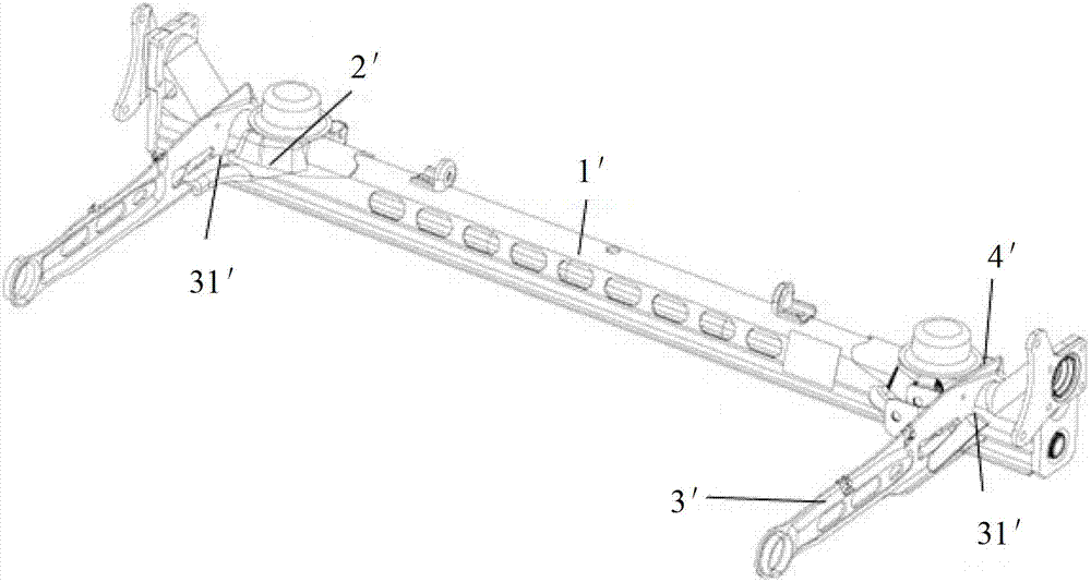
[0039] The horizontal direction mentioned in the embodiment of the present invention is the axial direction of the crossbeam assembly 1, the longitudinal direction is the direction perpendicular to the crossbeam assembly 1, and the direction where the trailing arm 3 is located in the figure is the front side of the crossbeam assembly 1, opposite It is the rear side of beam assembly 1.

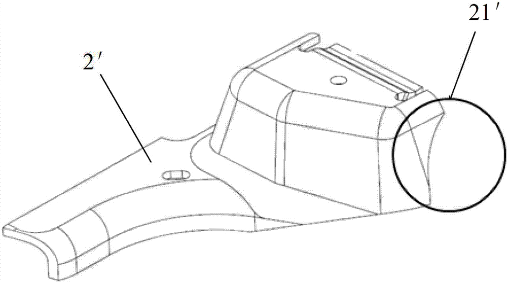
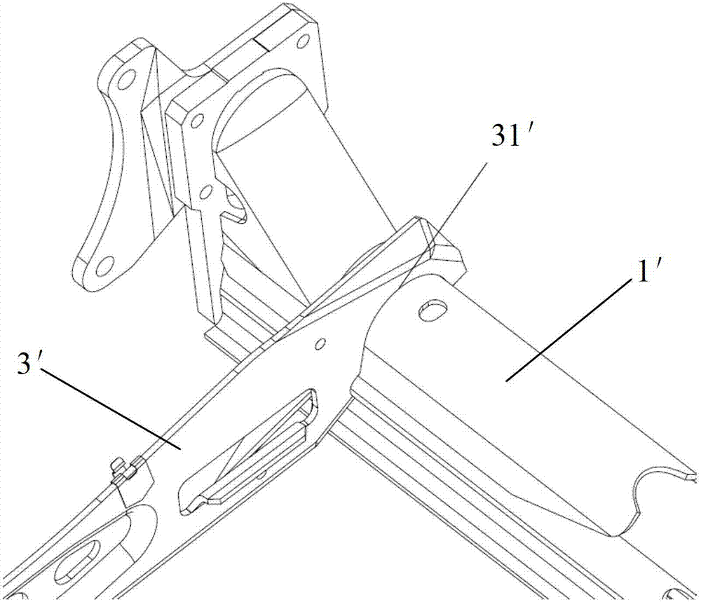
[0040] Such as Figure 2-3 As shown, the high-load rear axle includes a crossbeam assembly 1, a spring seat 2, a trailing arm 3 and a shock absorber support 4. The two trailing arms 3 are respectively arranged longitudinally along the two ends of the crossbeam assembly 1, and the two spring seats 2 are respectively Located on the inner side of the trailing arm 3 and installed on the upper surface of the beam assembly 1, two shock absorber brackets ...


PUM


Abstract

The technical scheme of the invention provides a high-load rear axle. The high-load rear axle comprises a beam assembly, spring seats, trailing arms, and shock absorber brackets; the two trailing arms are longitudinally arranged along the two ends of the beam assembly respectively; the two spring seats are respectively positioned inside the corresponding trailing arm and are arranged on the upper surface of the beam assembly; the two shock absorber brackets are respectively arranged at the positions, opposite to the spring seats, on the back side of the beam assembly; a first welding seam which longitudinally crosses over the beam assembly and is welded with the upper surface of the beam assembly is arranged on each spring seat. The first welding seam which longitudinally crosses over the beam assembly is arranged on each spring seat, so that the welding surfaces of the spring seats and the beam assembly are greatly increased, stress is favorable to be dispersed, the stability of a welding process is favorably improved, and the fatigue performance of each spring seat bearing high-load stress is facilitated.

Description

technical field [0001] The invention relates to the design of the automobile rear axle, in particular to a high-load rear axle. Background technique [0002] Due to the complex and poor road conditions in China, higher requirements are put forward for the durability of the rear axle of automobiles under high load conditions. Such as Figure 1A As shown, the traditional rear axle includes a crossbeam assembly 1' arranged in the transverse direction of the vehicle, a trailing arm 3' arranged longitudinally at both ends of the crossbeam assembly 1', and a spring seat 2 on the upper side of the two ends of the upper crossbeam assembly 1'. ', and the shock absorber bracket 4' arranged on the rear side of the two ends of the beam assembly 1'. The traditional rear axle is not optimized enough in terms of the sheet metal fit and weld arrangement of the components. The detailed analysis is as follows: [0003] Such as Figure 1B As shown, the traditional spring seat 2' is only wel...

Claims


Application Information

Patent Timeline
Patent Type & Authority Patents(China)
IPC IPC(8): B60G15/00B60B35/02
Inventor 黄承宗刘拥军陈璟何波
Owner SAIC GENERAL MOTORS
Why Eureka
Try Eureka