Hydraulic pump detection device for engineering construction machine

A detection device, technology of construction machinery

Active Publication Date: 2019-04-26
陈玉宏
View PDF7 Cites 0 Cited by
  • Summary
  • Abstract
  • Description
  • Claims
  • Application Information

AI Technical Summary

Problems solved by technology

[0002] The existing construction machinery hydraulic pump detection device rarely pays attention to the pollution of the hydraulic pump detection device itself when testing the hydraulic pump. In the workshop or other workplaces, the working environment is not very good, so the hydraulic pump When the detection device is idle, it is easy to fall into dust or oil, which will affect the use effect of the hydraulic pump detection device, and will also reduce the service life of the hydraulic pump detection device. Due to the heavy weight of the hydraulic pump detection device, the hydraulic pump detection device is also very difficult.

Method used


Image

  • Hydraulic pump detection device for engineering construction machine
  • Hydraulic pump detection device for engineering construction machine
  • Hydraulic pump detection device for engineering construction machine

Examples


Embodiment 1

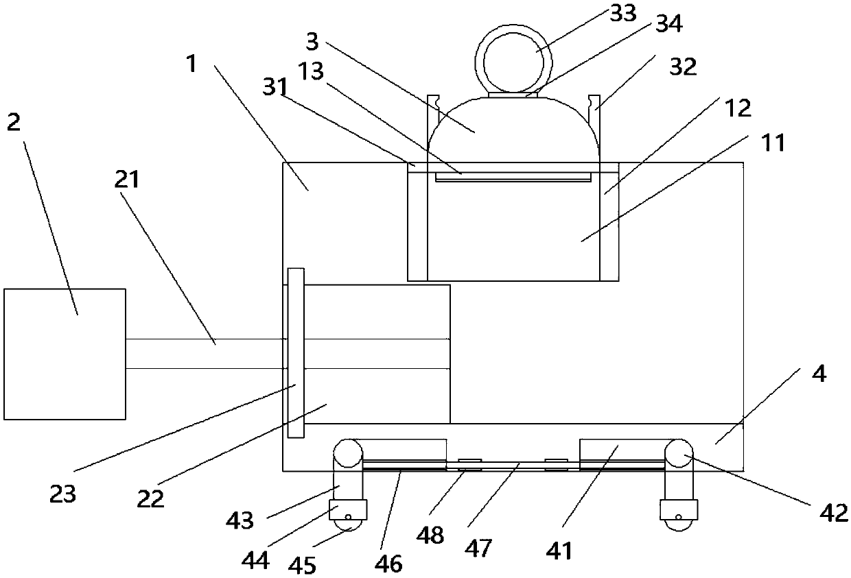
[0022] A hydraulic pump detection device for engineering construction machinery, comprising a box body 1, a detection device 2, a pressure gauge 3 and a base 4, such as figure 1 As shown, a pressure groove 11 is provided at the inner upper end of the box body 1, a pressure chute 12 is provided at both sides of the pressure groove 11, a pressure gauge 3 is provided at the upper end of the pressure groove 11, and a pressure gauge slider 31 is provided at both sides of the lower end of the pressure gauge 3, The pressure gauge slider 31 is slidably connected to the pressure chute 12, pressure gauge handles 32 are provided on both sides of the upper end of the pressure gauge 3, the upper end of the pressure gauge 3 is rotationally connected to the pressure gauge 33, and the left side of the box body 1 is provided with a detection device receiving groove 22, The right side of the detection device 2 is fixedly connected with the right side of the detection device accommodation groove ...

Embodiment 2

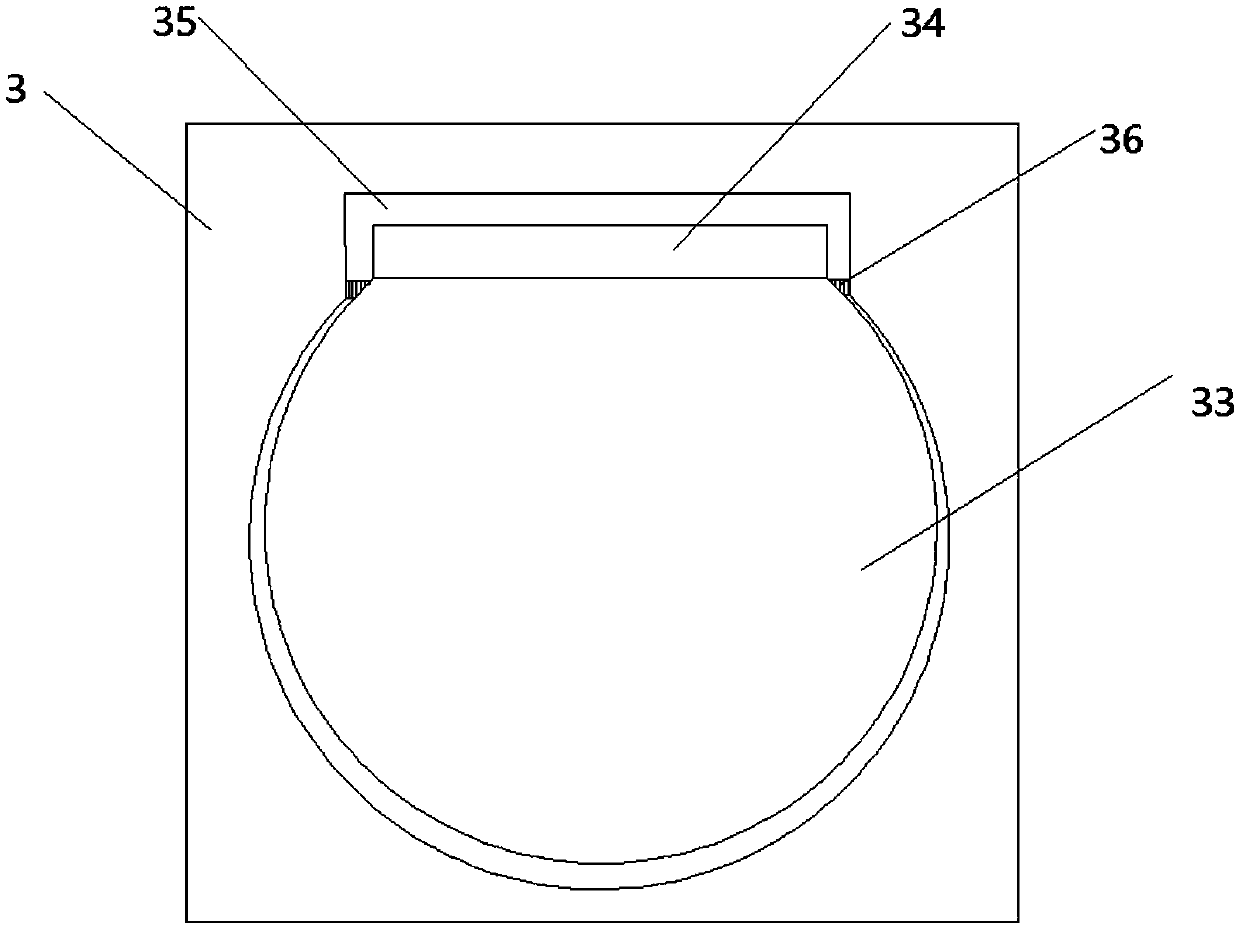
[0024] The difference between this embodiment and embodiment 1 is that, as figure 2 As shown, the upper end of the pressure gauge 3 is provided with a pressure gauge accommodation groove 35, the upper end of the pressure gauge accommodation groove 35 is rotationally connected with the rotating shaft 34, the rotating shaft 34 is fixedly connected with the pressure gauge 33, and the two sides of the pressure gauge accommodation groove 35 are provided with retaining springs 36.

[0025] When the pressure gauge is in use, the pressure gauge 33 is folded up, and the clamp spring 36 clamps the lower end of the pressure gauge 33 to clamp the pressure gauge on the upper end of the pressure gauge receiving groove 35. When not in use, press the clamp spring 36 to release the pressure. The gauge 33 is clamped in the pressure gauge accommodation groove 35 .

Embodiment 3

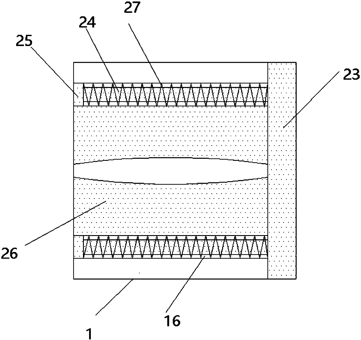
[0027] The difference between this embodiment and embodiment 1 is that, as image 3 As shown, in the middle of the left side of the accommodation groove limit plate 23, a limit clamp 26 is provided, and the box body 1 and the base 4 are provided with a limit plate chute 16, and the upper and lower ends of the limit plate 23 are fixedly connected to the limit column 24 on the left side, so that The left side of the position column 24 is fixedly connected with the limit block 25, and the limit block 25 is fixedly connected with the right side of the limit plate chute 16 through the spring 27.

[0028] When in use, pull the limit plate 23 of the receiving tank outward, take out the detection device 2, put the limit plate 23 back to its original position, pass the connecting line through the middle of the limit clamp plate 26, and connect the detection device 2 to the hydraulic pump out of the machine. Oil port for hydraulic pump pressure detection.


PUM


Abstract

The invention provides a hydraulic pump detection device for an engineering construction machine. The hydraulic pump detection device comprises a box body, a detection device body, a pressure instrument and a base; the upper end of the inner side of the body box is provided with a pressure tank of which the both sides are provided with pressure chutes, and the upper end of the pressure tank is provided with the pressure instrument; the both sides of the lower end of the pressure instrument are provided with pressure instrument sliding blocks, and the pressure instrument sliding blocks are connected with the pressure chutes slidably; the both sides of the upper end of the pressure instrument are provided with pressure instrument handles, and the upper end of the pressure instrument is connected with a pressure gauge rotatably; the left side of the box body is provided with a detection device body holding tank, and the right side of the detection device body is fixedly connected with theright side of the detection device body holding tank through a connecting line; the front end of the detection device body holding tank is slidably connected with a holding tank stop plate, and the lower end of the box body is fixedly provided with the base of which the inner side is provided with a folding clamping slot; and the base is connected with folding wheels rotatably. The device has theadvantages of easy use, long service life, convenient repair and maintenance, and convenient movement.

Description

technical field [0001] The invention relates to the technical field of engineering machinery, in particular to a hydraulic pump detection device for engineering construction machinery. Background technique [0002] The existing construction machinery hydraulic pump detection device rarely pays attention to the pollution of the hydraulic pump detection device itself when testing the hydraulic pump. In the workshop or other workplaces, the working environment is not very good, so the hydraulic pump When the detection device is idle, it is easy to fall into dust or oil, which will affect the use effect of the hydraulic pump detection device, and will also reduce the service life of the hydraulic pump detection device. Due to the heavy weight of the hydraulic pump detection device, the hydraulic pump detection device is also very difficult. . Contents of the invention [0003] The technical problem to be solved by the present invention is to provide a hydraulic pump detection...

Claims


Application Information

Patent Timeline
IPC IPC(8): F04B51/00
CPCF04B51/00
Inventor 陈玉宏陈思晟
Owner 陈玉宏
Why Eureka
Try Eureka