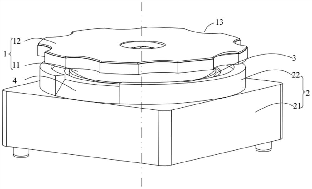
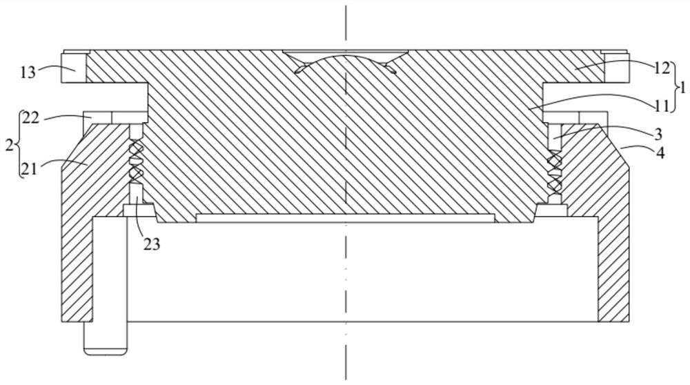
A lens module

A lens module and lens technology, applied in the field of optics, can solve the problems of lens dispensing, affecting the appearance of the lens module, glue overflow, etc., so as to improve cleanliness and aesthetics, reduce lens offset and out of focus, and enhance The effect of bonding firmness

Active Publication Date: 2021-11-12
GUANGZHOU LUXVISIONS INNOVATION TECH LTD
View PDF5 Cites 0 Cited by
  • Summary
  • Abstract
  • Description
  • Claims
  • Application Information

AI Technical Summary

Problems solved by technology

Since the lens covers the dispensing groove of the lens barrel, the glue cannot be dispensed from the top surface of the lens, only from the side
However, the distance between the lens and the top of the lens barrel is less than 0.5mm, and it is difficult for the operator to dispense glue, so that the glue needle used for gluing cannot be fully inserted into the glue groove, and the glue cannot completely flow into the glue groove, and the glue can only be applied on the lens. On the side wall of the barrel, the glue will overflow on the surface of the lens and lens barrel, seriously affecting the appearance of the lens module
In order to solve the problem of glue overflow, we can only take measures to reduce the amount of glue dispensed. However, after the glue that completely flows into the glue tank is reduced, the torque of the lens after dispensing glue will be small, which will cause the lens to shift in the actual use of the lens module. problems, resulting in poor image quality

Method used


Image

  • A lens module
  • A lens module

Examples


Embodiment Construction

[0024] In order to make the technical problems solved by the present invention, the technical solutions adopted and the technical effects achieved clearer, the technical solutions of the embodiments of the present invention will be further described in detail below in conjunction with the accompanying drawings. Obviously, the described embodiments are only the technical solutions of the present invention. Some, but not all, embodiments. Based on the embodiments of the present invention, all other embodiments obtained by those skilled in the art without creative efforts fall within the protection scope of the present invention.

[0025] In the description of the present invention, unless otherwise clearly specified and limited, the terms "connected", "connected" and "fixed" should be understood in a broad sense, for example, it can be a fixed connection, a detachable connection, or an integrated ; It can be a mechanical connection or an electrical connection; it can be a direct...


PUM


Abstract

The invention belongs to the field of optical technology and discloses a lens module. The lens module includes a lens and a lens barrel that are connected to each other. A glue groove is formed between the lens and the lens barrel. An avoidance groove is opened on the side wall of the lens barrel. The bottom of the avoidance groove and the central axis of the lens barrel are set at an angle. , and the distance between the bottom of the avoidance groove and the central axis of the lens barrel decreases gradually along the direction approaching the lens. The lens module has an avoidance groove on the side wall of the lens barrel, so that the glue needle can be inserted into the glue groove and injected, reducing the situation that the glue will overflow on the surface of the lens and lens barrel, thereby improving the lens module. The cleanliness and aesthetics of the group; and the glue can completely enter the glue groove for bonding between the lens and the lens barrel. The glue is sufficient, which enhances the firmness of the bond, and makes the torque of the lens larger after dispensing, reducing the actual use During the process, the lens shifted and out of focus, which improved the image quality.

Description

technical field [0001] The invention relates to the field of optical technology, in particular to a lens module. Background technique [0002] With the rapid development of multimedia technology, digital cameras, video cameras and mobile phones with cameras are more and more popular among consumers. Therefore, the demand for lens module products is gradually increasing, and higher requirements are put forward. [0003] Existing lens modules mainly include a lens and a lens barrel, which need to be bonded with glue. Since the lens covers the dispensing groove of the lens barrel, glue cannot be dispensed from the top surface of the lens, but can only be dispensed from the side. However, the distance between the lens and the top of the lens barrel is less than 0.5mm, and it is difficult for the operator to dispense glue, so that the glue needle used for gluing cannot be fully inserted into the glue groove, and the glue cannot completely flow into the glue groove, and the glue ...

Claims


Application Information

Patent Timeline
Patent Type & Authority Patents(China)
IPC IPC(8): G02B7/02G03B30/00
CPCG02B7/025
Inventor 肖强杜海朝
Owner GUANGZHOU LUXVISIONS INNOVATION TECH LTD
Why Eureka
Try Eureka