
Charge and discharge system and control method thereof

A charge-discharge and charge-discharge interface technology, applied in the field of new energy vehicle charging, can solve the problem of low utilization rate of charging equipment

Inactive Publication Date: 2019-04-26
PUTIAN NEW ENERGY +1
View PDF5 Cites 0 Cited by
  • Summary
  • Abstract
  • Description
  • Claims
  • Application Information

AI Technical Summary

Problems solved by technology

[0004] During the charging process of the existing two-way charging equipment, a single gun outputs, and the utilization rate of the charging equipment is low

Method used


Image

  • Charge and discharge system and control method thereof
  • Charge and discharge system and control method thereof

Examples


Embodiment Construction

[0015] The following will clearly and completely describe the technical solutions in the embodiments of the present application with reference to the drawings in the embodiments of the present application. The described embodiments are only some of the embodiments of the present application, not all of them. Based on the embodiments in this application, all other embodiments obtained by persons of ordinary skill in the art without making creative efforts belong to the scope of protection of this application.

[0016] The principle and spirit of the present application will be explained in detail below with reference to several representative implementations of the present application.

[0017] Although the present application provides method operation steps or device structures as shown in the following embodiments or accompanying drawings, more or less operation steps or module units may be included in the method or device based on conventional or creative work . In the step...


PUM


Abstract

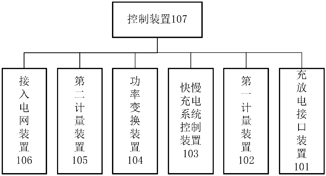
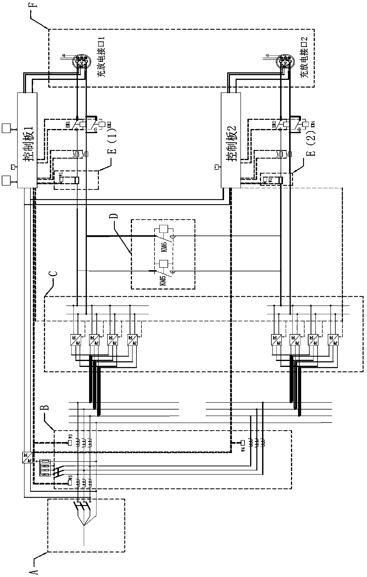
The invention discloses a charge and discharge system and a control method thereof. The system includes a charge and discharge interface device, a control device, a fast and slow charge and dischargesystem control device and a grid access device. The control device is configured to control the grid access device, and the fast and slow charge and discharge system control device performs charging and discharging through the charge and discharge interface device. The control device controls a contactor of the fast and slow charge and discharge system control device to be closed when the charge and discharge interface device is connected to a single gun and the charge and discharge required power exceeds a set threshold and controls the contactor in the fast and slow charge and discharge system control device to be open when the charge and discharge interface device is connected to the single gun and the charge and discharge required power is lower than the set threshold or the charge anddischarge interface device is connected to double guns. Therefore, two-way charging and discharging of a double-gun charge interface can be achieved.

Description

technical field [0001] The present application relates to the technical field of new energy vehicle charging, in particular to a charging and discharging system and a control method thereof. Background technique [0002] This section is intended to provide a background or context to the embodiments of the application that are recited in the claims. The descriptions herein are not admitted to be prior art by inclusion in this section. [0003] Vehicle to grid (V2G) technology of electric vehicles refers to the technology that electric vehicles send power to the grid. Its core idea is to use a large number of electric vehicle energy storage as a buffer for the grid and renewable energy. Vehicle-to-grid technology is attracting widespread attention. Through V2G, the problems of low grid efficiency and fluctuations in renewable energy can be alleviated to a large extent, and it can also create benefits for electric vehicle users. [0004] During the charging process of the exi...

Claims


Application Information

Patent Timeline
Patent Type & Authority Applications(China)
IPC IPC(8): H02J3/32B60L55/00
CPCH02J3/32
Inventor 白鸥武圣彭博刘文珍邵浙海邓迟
Owner PUTIAN NEW ENERGY
Learn More