Grass cutting head and grass trimmer

A technology for mowing heads and mowing ropes, which is applied to agricultural machinery and implements, hand-held lawn trimmers, harvesters, etc., and can solve problems such as reducing work efficiency, reducing the service life of mowers, and winding on one side

Active Publication Date: 2019-04-30
NANJING CHERVON IND
View PDF5 Cites 2 Cited by
  • Summary
  • Abstract
  • Description
  • Claims
  • Application Information

AI Technical Summary

Problems solved by technology

At present, in order to wind the trimming rope to the spool, the user usually needs to remove the spool and manually wind the trimming rope. Obviously, such an operation is time-consuming and laborious, and reduces work efficiency.
For this reason, there is also a mowing head on the market that can wind the mowing rope to the spool without disassembling the spool. However, the user still needs to manually turn a certain part on the mowing head to drive the spool to rotate so as to wind the mowing rope to the spool. The rope is wound to the spool, and the user will still feel tired in the long run
[0003] In the existing mowers, when manual winding is required, the user usually needs to hold the head shell with one hand and the operating part with the other hand. In this way, the user needs to operate with both hands at the same time, which will cause the mowing rope to be wound up to on the arm, causing interruption of the winding process
Moreover, when winding the wire, the bobbin will move up and down in the axial direction, which will easily cause the problem of one-sided winding
[0004] Furthermore, the size of the operating parts for the user to operate in the mowing head is usually relatively small, and serious wear and tear between the operating parts and the ground is likely to occur, thereby reducing the service life of the mowing machine
[0005] In addition, in order to align the outer hole and the inner hole of the mowing head, the user needs to adjust the alignment of the inner hole and the outer hole before threading, thereby reducing the work efficiency

Method used


Image

  • Grass cutting head and grass trimmer
  • Grass cutting head and grass trimmer
  • Grass cutting head and grass trimmer

Examples


Embodiment Construction

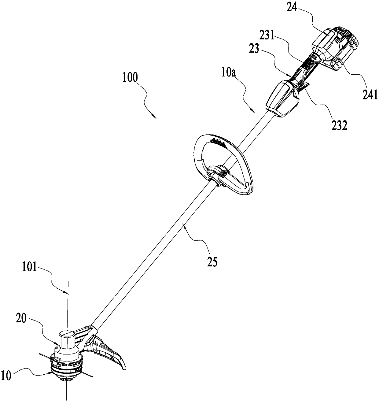
[0053] figure 1 The shown lawnmower 100 installed with the mowing head 10 is used as a lawn trimming tool for the user to mow grass or trim vegetation or trim the lawn. Such as figure 1 As shown, the mowing machine 100 includes: a mowing head 10 and a mowing host 10 a, and the mowing host 10 a includes: a driving device 20 , an operating device 23 , a power supply device 24 and a connecting device 25 . Wherein, the operating device 23 may include a handle 231 for the user to hold, and may also include a main switch 232 for starting the mower 100 to mow grass. The power supply device 24 may include a battery pack 241 for supplying electric power.

[0054] The mowing head 10 is used for mowing grass, the driving device 20 is used to drive the mowing head 10 to rotate around the axis of rotation 101, the operating device 23 is used for the user to operate to control the mowing machine 100, and the power supply device 24 is used to power the driving device. 20 provides a power ...


PUM


Abstract

The invention discloses a grass cutting head and a grass trimmer. The grass cutting head includes a spool and a head shell, the spool is provided with inner holes, and the head shell is provided withouter holes; the head shell includes a first housing portion and a second housing portion that are detachably connected, and when the first housing portion and the second housing portion are connectedand surrounded, an accommodation space used for accommodating at least part of the spool is formed; the grass cutting head also includes an operating member connected to the second housing portion; the operating member includes an operating portion that at least partially protrudes to the outside of the accommodation space for a user to operate; and guiding portions are also formed on the operating member, an integral body formed by the operating member and the second housing portion is installed on the first housing portion, the guiding portions guide the spool to rotate with a first axis asa shaft to a line plugging position where at least part of the inner holes and the outer holes are aligned with each other. When the grass cutting head closes a cover, the inner holes can be automatically aligned with the outer holes.

Description

technical field [0001] The invention relates to a garden tool, in particular to a mowing head and a mowing machine. Background technique [0002] As a kind of lawn trimming tool in a kind of garden class tool, mower has been widely paid attention to by people. Usually, the mowing machine includes a mowing head for mowing grass, and a spool for winding the mowing rope is arranged in the mowing head. At present, in order to wind the trimming rope to the spool, the user usually needs to remove the spool and manually wind the trimming rope. Obviously, such an operation is time-consuming and laborious, and reduces work efficiency. For this reason, there is also a mowing head on the market that can wind the mowing rope to the spool without disassembling the spool. However, the user still needs to manually turn a certain part on the mowing head to drive the spool to rotate so as to wind the mowing rope to the spool. The cord winds up to the spool, which can still be tiring for th...

Claims


Application Information

Patent Timeline
Patent Type & Authority Applications(China)
IPC IPC(8): A01D34/416
CPCA01G3/067A01D34/416A01D34/90A01G3/06A01D34/4162A01D34/4163
Inventor 郭建朋王桑龙陈龙海张棋王浩山冈敏成聂方杰
Owner NANJING CHERVON IND
Why Eureka
Try Eureka