Automatic straightening device for leg wire of electronic detonator

A straightening device and electronic detonator technology, applied in the field of civil explosives, can solve problems such as not suitable for mass production, affecting product qualification rate, and finger wear

Pending Publication Date: 2021-05-18
杭州晋旗电子科技有限公司
View PDF0 Cites 1 Cited by
  • Summary
  • Abstract
  • Description
  • Claims
  • Application Information

AI Technical Summary

Problems solved by technology

[0002] In the field of electronic detonator production, the current wire straightening process before the riveting assembly of the electronic detonator leg wire and the control chip is that the operator straightens the leg wire by hand, and finally puts it into the control chip docking groove for riveting assembly. The method wears a lot on the fingers of the operator, and sometimes hurts the fingers. In many cases, the straightening effect is not good, and the butt joint is not in place during the riveting process, resulting in unqualified riveting products, which affects the product qualification rate of the station. , which seriously affects the production efficiency of the riveted control chip
[0003] At present, the straightening method of the foot line is mainly operated manually by the operator, which is labor-intensive and low in production efficiency, and is not suitable for the production of mass products.

Method used


Image

  • Automatic straightening device for leg wire of electronic detonator
  • Automatic straightening device for leg wire of electronic detonator
  • Automatic straightening device for leg wire of electronic detonator

Examples


Embodiment Construction

[0018] The following will clearly and completely describe the technical solutions in the embodiments of the present invention with reference to the accompanying drawings in the embodiments of the present invention. Obviously, the described embodiments are only some, not all, embodiments of the present invention. Based on the embodiments of the present invention, all other embodiments obtained by persons of ordinary skill in the art without making creative efforts belong to the protection scope of the present invention.

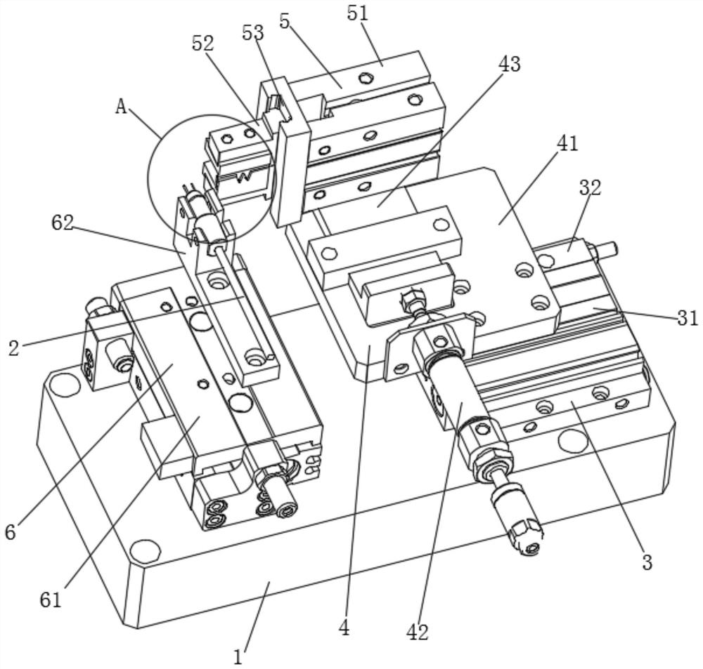
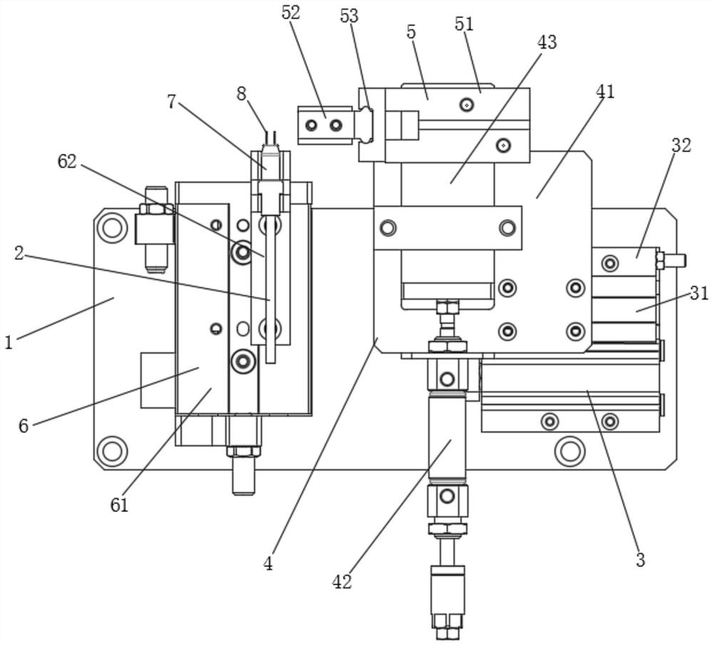
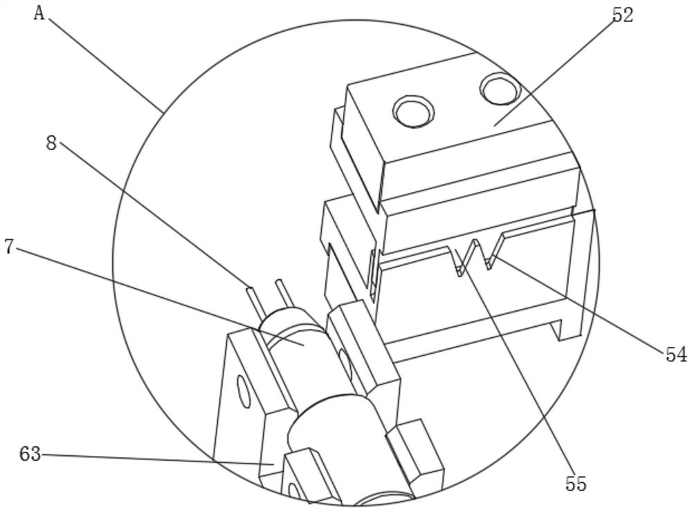
[0019] see Figure 1-3 , the present invention provides a technical solution: an electronic detonator leg line automatic straightening device, including a base plate 1 and a leg line 2, the end of the leg line 2 is a sealing plug 7 and a butt wire 8, and the base plate 1 is equipped with a foot The line positioning mechanism 6 and the alignment mechanism 3, the sealing plug 7 of the foot line 2 is clamped on the foot line positioning mechanism 6, the foot line...


PUM


Abstract

The invention discloses an automatic straightening device for a leg wire of an electronic detonator. The automatic straightening device for the leg wire of the electronic detonator comprises a bottom plate and the leg wire, a sealing plug and a butt joint iron wire are arranged at the end part of the leg wire, a leg wire positioning mechanism and a straightening and receding mechanism are installed on the bottom plate, the sealing plug of the leg wire is arranged on the leg wire positioning mechanism in a clamped mode, a straightening and stretching mechanism is movably arranged on the straightening and receding mechanism, the moving direction of the straightening and stretching mechanism is perpendicular to the central axis of the leg wire, and a straightening and clamping mechanism is movably arranged at the position, close to the butt joint iron wire, of the straightening and stretching mechanism. According to the automatic straightening device for the leg wire of the electronic detonator, the function of automatically straightening the butt joint iron wire before the leg wire of the electronic detonator is connected with a control chip in a riveted mode can be realized, mechanical action is adopted to automatically pull the bent and deformed iron wire exposed out of the sealing plug of the leg wire of the electronic detonator, the purpose of automatically straightening the leg wire is achieved, defective products caused by inconsistent straightening shapes due to different operators are avoided, the production efficiency of equipment is improved, manpower is replaced, and the safety coefficient is improved.

Description

technical field [0001] The invention relates to the technical field of civil explosives, in particular to an automatic straightening device for electronic detonator legs. Background technique [0002] In the field of electronic detonator production, the current wire straightening process before the riveting assembly of the electronic detonator leg wire and the control chip is that the operator straightens the leg wire by hand, and finally puts it into the control chip docking groove for riveting assembly. The method wears a lot on the fingers of the operator, and sometimes hurts the fingers. In many cases, the straightening effect is not good, and the butt joint is not in place during the riveting process, resulting in unqualified riveting products, which affects the product qualification rate of the station. , has a strong impact on the production efficiency of the riveting control chip of the pin line. [0003] At present, the straightening method of the foot line is main...

Claims


Application Information

Patent Timeline
Patent Type & Authority Applications(China)
IPC IPC(8): B21F1/02
CPCB21F1/02
Inventor 张小江李叶森何锦周坤常光均
Owner 杭州晋旗电子科技有限公司
Why Eureka
Try Eureka