Heliostat hoisting device

A hoisting device and heliostat technology, applied in the direction of transportation and packaging, load hanging components, etc., can solve the problems of assembly hazards, unsuitable for manual on-site assembly work, and unsmooth alignment between the connecting seat and the installation column surface, etc.

Active Publication Date: 2019-04-26
ZHEJIANG SUPCON SOLAR TECHNOLOGY CO LTD
View PDF5 Cites 1 Cited by
  • Summary
  • Abstract
  • Description
  • Claims
  • Application Information

AI Technical Summary

Problems solved by technology

[0007] However, at this stage, the single heliostat in the existing actual photothermal projects often reaches more than 20 square meters, and the weight of the single glass also increases accordingly, and the assembly is also very dangerous, which is no longer suitable for manual on-site assembly work; The length of the heliostat spreader is often more than 10 meters, and the weight is heavy. The lifting method of moving the spreader from the side to the fixed position of the heliostat is time-consuming and laborious, and it is easy to damage the heliostat; at the same time, the existing heliostat hoisting device , when hoisting, it is necessary to adjust the position of the spreader so that it can be fixed with the heliostat. Since the heliostat and the spreader are very large, it is very inconvenient to adjust the fixed position, which seriously affects the efficiency of lifting; at the same time, it is necessary to constantly adjust the two In addition, during the hoisting process of the existing heliostat, the connecting seat connecting the heliostat and the installation column will be hoisted together with the heliostat, so as to speed up the overall heliostat installation. installation speed of
However, in the existing hoisting schemes, it is impossible to perform an overall leveling of the heliostat during hoisting (that is, keep the mirror surface of the heliostat parallel to the mounting surface of the lifting lug of the lifting frame), so that the horizontal plane of the hoisting frame and the bottom of the connecting seat are installed The surface cannot be kept relatively parallel, which eventually leads to the inability to align the connecting seat and the installation column surface smoothly, which greatly reduces the overall installation efficiency of the heliostat

Method used


Image

  • Heliostat hoisting device
  • Heliostat hoisting device
  • Heliostat hoisting device

Examples


Embodiment

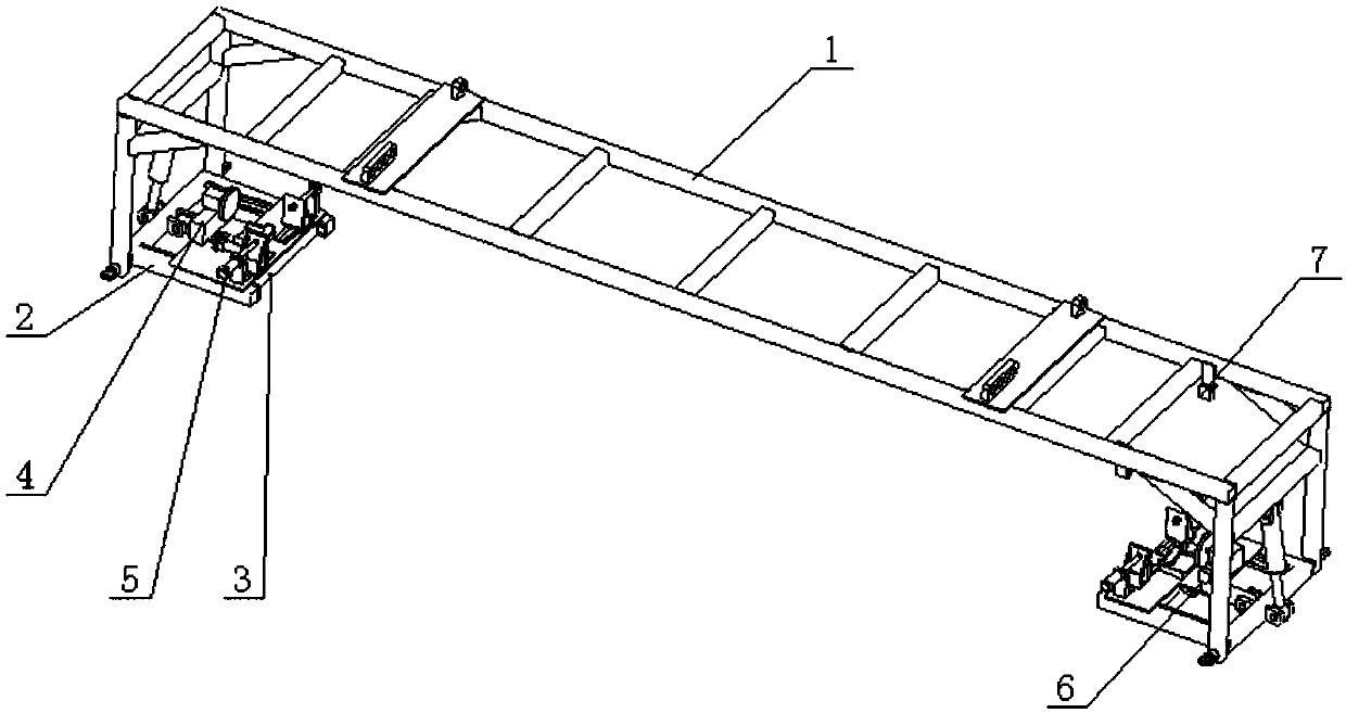
[0073] Such as figure 1 As shown, the heliostat hoisting device provided in this embodiment includes:

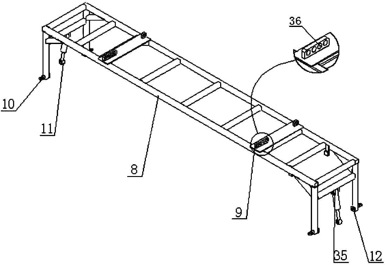
[0074] Lifting frame 1, please go to see figure 2 The lifting frame 1 is mainly composed of a main frame 8, lifting ears 9, side lifting rings 10, turning drive 11, turning support 12, and turning ear seat B 35. Specifically, the main frame 8 is formed by group welding of profiles, and the lifting lugs 9 are respectively symmetrically welded to the left and right 4 positions of the main frame 8. At the same time, the lifting lugs 9 are provided with several groups of lifting holes 36, and the side The hanging rings 10 are respectively hinged on the outer four sides of the root of the main frame 8. The turning drive 11 is hinged to the main frame 8 through the turning pin and the turning lug B 35, and the turning supports 12 are respectively provided In the four positions inside the bottom of the main frame 8; the driving form of the turning drive 11 is not limited to the drivi...


PUM


Abstract

The invention discloses a heliostat hoisting device. The hoisting device comprises a hoisting frame, overturning frames, push mechanisms, leveling mechanisms, locating and locking anti-rotation mechanisms, position detection sensor modules and leveling sensor modules. The hoisting frame of the hoisting device is composed of a main frame, hoisting lugs, side hanging rings, overturning drivers, overturning supports and overturning lug seats B. The hoisting frame is hinged to all the overturning frames through rotating shafts, the overturning drivers and the like. All the overturning frames can rotate freely within the range from 0 degree to 90 degrees through the overturning drivers and are linked with the push mechanisms through sliding modules and push drivers correspondingly. Each push mechanism can slide in a plane of the corresponding overturning frame. The locating and locking anti-rotation mechanisms and the leveling mechanisms are mounted on the push mechanisms through bottom attachment plates. The position detection sensor modules are mounted on the bottom attachment plates. The leveling sensor modules are arranged on the main frame and used for detecting the left-right height of heliostats and feeding back to the leveling mechanisms to execute relevant actions.

Description

Technical field [0001] The invention relates to the field of solar thermal power generation, to a tower-type solar thermal power generation system, and in particular to a hoisting device for a heliostat. Background technique [0002] As the economy continues to develop, energy is increasingly scarce, traditional non-renewable energy is increasingly depleted, and economic development is increasingly restricted by the development and utilization of energy. The utilization of renewable energy has attracted widespread attention, especially the use of solar energy. [0003] Solar thermal power generation is currently a major method of solar energy utilization. The current solar thermal power generation can be divided into (1) tower solar thermal power generation; (2) trough solar thermal power generation; (3) dish solar thermal power generation according to solar energy collection methods. [0004] In the field of solar thermal power generation, tower solar thermal power generation has t...

Claims


Application Information

Patent Timeline
Patent Type & Authority Applications(China)
IPC IPC(8): B66C13/08B66C13/16B66C1/28
CPCB66C1/28B66C13/085B66C13/16
Inventor 王李波张旭中毛永夫肖婷婷陈康立谢莹吴松敏
Owner ZHEJIANG SUPCON SOLAR TECHNOLOGY CO LTD
Why Eureka
Try Eureka