Steel grating through-type drifting clamping feeding mechanism

A floating clamping and feeding mechanism technology, applied in metal processing, attachments of sawing machines, metal sawing equipment, etc., can solve the problems of wasting time, poor process continuity, and low production efficiency.

Inactive Publication Date: 2017-06-20
YANTAI XINKE STEEL STRUCTURE
View PDF6 Cites 3 Cited by
  • Summary
  • Abstract
  • Description
  • Claims
  • Application Information

AI Technical Summary

Problems solved by technology

[0003] The purpose of the present invention is to propose a steel grating passing floating clamping feeding mechanism to solve the process caused by lifting the steel grating from the previous process and placing it on the feeder when the steel grating is cut to length in the background technology. Poor coherence, waste of time, waste of manpower, and low production efficiency

Method used


Image

  • Steel grating through-type drifting clamping feeding mechanism
  • Steel grating through-type drifting clamping feeding mechanism
  • Steel grating through-type drifting clamping feeding mechanism

Examples


Embodiment Construction

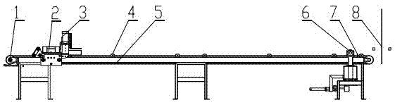
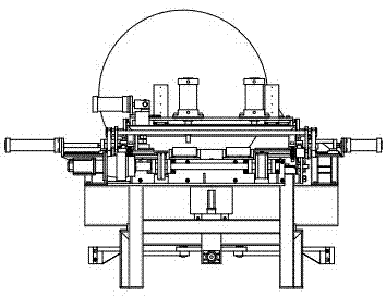
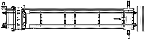
[0005] refer to figure 1 , figure 2 , image 3 , Figure 4 , Figure 5 , a steel grating passing floating clamping feeding mechanism, characterized in that the servo transmission mechanism 1 drives the feeding trolley 2 to move forward and backward along the feeding platform 5, the conveying roller table 4 is arranged on the feeding platform 5, and the clamping on the feeding trolley 2 The steel grating mechanism 3 is a horizontal U-shaped clamp on both sides. The position of the lower clamping plate of the U-shaped clamp is lower than the upper cut surface of the conveying roller table 4, so that the conveyed steel grating can pass through the U-shaped clamp, and the power controls the U-shaped clamp. Clamping and fixing up and down; the clamping steel grating mechanism 3 on the feeding trolley 2 is a horizontal U-shaped fixture on both sides, and the U-shaped fixture on one side can move along the A slide rail 18 under the drive of the A cylinder 19, so that It clamps h...


PUM


Abstract

The present invention relates to a steel grating through-type drifting clamping feeding mechanism. The problems to be solved are poor procedure continuity, time waste, labor waste, and low production efficiency due to that a welded steel grating may not be directly delivered to a pit-saw cutting table. The technical solution employed to solve the technical problems has the following key points: a servo drive mechanism drives a feeding trolley to move backward and forward along a feeding platform; a rollgang is disposed on the feeding platform; a steel grating clamping mechanism on the feeding trolley consists of horizontal U-shaped clamps on both sides, and a lower clamping plate of each U-shaped clamp is lower in position than the upper tangent-plane of the rollgang so that the conveyed steel grating can pass through the U-shaped clamp. The U-shaped clamps are controlled by power to clamp and fix up and down. The steel grating through-type drifting clamping feeding mechanism is applicable to steel grating production.

Description

technical field [0001] The invention belongs to mechanical processing equipment, in particular to a steel grating passing floating clamping feeding mechanism. Background technique [0002] The steel grating is a grid-shaped plate that is welded together by a flat steel and a cross bar through a pressure resistance welding machine. After welding and cutting off the flat steel heads on both sides, the feeding mechanism pinches the steel grating and cuts it to a certain length through a cutting saw. The original pinching equipment cannot allow the steel grating of the previous process to pass directly from the rear, and the steel grating of the previous process must be lifted and placed on the feeding mechanism. This results in poor continuity of the process, a waste of time, a waste of manpower, and low production efficiency. Contents of the invention [0003] The purpose of the present invention is to propose a steel grating passing floating clamping feeding mechanism to s...

Claims


Application Information

Patent Timeline
Patent Type & Authority Applications(China)
IPC IPC(8): B23Q7/04B23Q7/05B23Q7/08B23D59/00
CPCB23Q7/055B23D59/00B23Q7/043B23Q7/08
Inventor 张军强初文博
Owner YANTAI XINKE STEEL STRUCTURE
Why Eureka
Try Eureka