
Projector supporting frame for teaching

A projector and external support technology, applied in the field of teaching equipment, can solve the problems of projector drop, loss, troublesome fixing and dismounting of the projector, etc., and achieve the effects of convenient installation and disassembly, prevention of falling damage, and saving operation time

Active Publication Date: 2019-04-30
BINZHOU POLYTECHNIC
View PDF12 Cites 12 Cited by
  • Summary
  • Abstract
  • Description
  • Claims
  • Application Information

AI Technical Summary

Problems solved by technology

[0002] A projector is an optical instrument that uses optical elements to enlarge the contour of a workpiece and projects it onto a video screen. It can use transmitted light for contour measurement, and can also use reflected light to measure the surface shape of a non-through hole and observe the surface of a part. Teaching The projector is commonly used, and the installation of the projector is usually fixed on the projector bracket, but the traditional projector bracket is very inconvenient for the height adjustment and angle adjustment of the projector; the projector is installed on the bracket, without The storage structure stores it, and it is easy to accumulate dust when it is placed. When the projector is not in use, people walk around and easily knock over the bracket, causing the projector to fall and cause losses; moreover, the traditional projector bracket is difficult for fixing and disassembling the projector. It is very troublesome and reduces the efficiency of disassembly; therefore, it is necessary to invent a teaching projector bracket to solve the above problems

Method used


Image

  • Projector supporting frame for teaching
  • Projector supporting frame for teaching
  • Projector supporting frame for teaching

Examples


Embodiment Construction

[0021] The following will clearly and completely describe the technical solutions in the embodiments of the present invention with reference to the accompanying drawings in the embodiments of the present invention. Obviously, the described embodiments are only some, not all, embodiments of the present invention. Based on the embodiments of the present invention, all other embodiments obtained by persons of ordinary skill in the art without making creative efforts belong to the protection scope of the present invention.

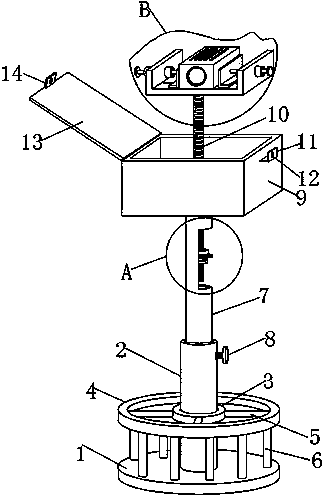
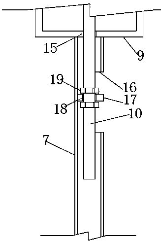
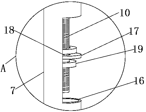
[0022] The present invention provides such Figure 1-5 The shown projector bracket for teaching includes a bottom support disc 1, a support round tube 2 is welded and fixed in the middle of the upper end of the bottom support disc 1, and an inner collar 3 is fixedly sleeved in the outer middle of the support round tube 2, An outer support ring 4 is arranged above the bottom support disc 1, and the inner wall of the outer support ring 4 and the outer wall of th...


PUM


Abstract

The invention discloses a projector supporting frame for teaching, and belongs to the field of educational appliances. The projector supporting frame for the teaching comprises a bottom supporting disc, wherein a supporting circular pipe is fixedly welded to the middle part of the upper end of the bottom supporting disc; a receiving box is fixedly connected to the upper end of the supporting circular pipe; an adjusting threaded rod is inserted in an upper circular hole; the lower end of the adjusting threaded rod penetrates through a lower circular hole; a U-shaped mounting plate is fixedly welded to the upper end of the adjusting threaded rod; L-shaped clamping plates are correspondingly and movably arranged on the two sides of the upper end of a transverse plate of the U-shaped mountingplate; a projector body is clamped between the two L-shaped clamping plates; and a movable reverse cover is hinged to one side of the upper end of the receiving box. According to the projector supporting frame, the projector is convenient to fix and disassemble, the height and the angle of the projector can be adjusted, at the same time, the projector can be received, and very good dust-proof andprotective effects on the projector can be realized.

Description

technical field [0001] The invention relates to the field of teaching appliances, in particular to a teaching projector bracket. Background technique [0002] A projector is an optical instrument that uses optical elements to enlarge the contour of a workpiece and projects it onto a video screen. It can use transmitted light for contour measurement, and can also use reflected light to measure the surface shape of a non-through hole and observe the surface of a part. Teaching The projector is commonly used, and the installation of the projector is usually fixed on the projector bracket, but the traditional projector bracket is very inconvenient for the height adjustment and angle adjustment of the projector; the projector is installed on the bracket, without The storage structure stores it, and it is easy to accumulate dust when it is placed. When the projector is not in use, people walk around and easily knock over the bracket, causing the projector to fall and cause losses;...

Claims


Application Information

Patent Timeline
IPC IPC(8): F16M11/28F16M11/20F16M11/04G03B21/14G03B21/54
CPCF16M11/041F16M11/2014F16M11/28G03B21/145G03B21/54
Inventor 汤亮
Owner BINZHOU POLYTECHNIC
Learn More