

Method and system for monitoring and monitoring a knife switch control loop
A technology of control loop and detection method, applied in the field of electric power, can solve the problems of operation delay, the control loop cannot be found by the knife switch, etc., and achieve the effect of reducing operation delay, speeding up search time, and fast positioning
Active Publication Date: 2021-06-15
中国南方电网有限责任公司超高压输电公司南宁监控中心
View PDF0 Cites 0 Cited by
- Summary
- Abstract
- Description
- Claims
- Application Information
AI Technical Summary
Problems solved by technology
Different from the switch which has a complete control circuit disconnection monitoring circuit, all current knife switches do not have a monitoring circuit. As a result, the control circuit cannot be found to have problems under the operating condition of the knife switch. It can only be found at the moment of operation, resulting in operation delays.
Method used
View moreImage
Smart ImageViewing Examples

Examples
Embodiment
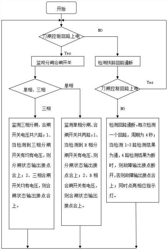
[0027] refer to figure 1 As shown, the knife switch control loop monitoring method provided in this embodiment includes:
Login to View More PUM
 Abstract
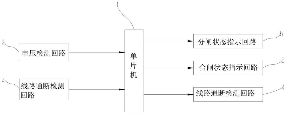
The invention discloses a method and system for monitoring and detecting a knife switch control circuit. The method includes: detecting and judging whether the knife switch control circuit is powered off; State monitoring, judging whether the opening and closing circuit is connected, meeting the conditions for opening and closing operation, and outputting a status indication; Whether each segment of the closing control circuit should be connected is in the connected state, and the segment that should not be connected is in the non-connected state, and the status indication is output. By adopting this method, the opening and closing circuit status of the knife switch control circuit can be monitored, and the circuit fault can be found before the knife switch is operated, so that the knife switch also has the circuit disconnection monitoring function of the same level as the switch, and when there is a problem It can realize the fault detection of the knife switch control circuit and quickly locate the faulty section of the circuit, thereby reducing operation delays.
Description
technical field [0001] The invention relates to the field of electric power technology, in particular to a monitoring system and a monitoring method for a knife switch control circuit. Background technique [0002] Knife switch failure is the most frequently encountered and most common failure in switching operations, and the operation delay caused by knife switch failure accounts for the largest part of the operation delay. Knife switch faults are divided into mechanical faults and circuit faults, and circuit faults account for about half of them. Different from the switch which has a complete control circuit disconnection monitoring circuit, all the current knife switches do not have a monitoring circuit, which leads to the failure of the control circuit to be found under the operating condition of the knife switch. It can only be found at the moment of operation, resulting in operation delays. . Contents of the invention [0003] The purpose of the present invention i...
Claims
Login to View More Application Information
Patent Timeline
 Patent Type & AuthorityPatents(China)
IPC IPC(8): G01R31/327G01R31/54
CPCG01R31/327G01R31/50
Inventor廖华钟文明滕永泰朱明红袁卫义陈方之钟晖彭伟梁阳陈磊
Owner中国南方电网有限责任公司超高压输电公司南宁监控中心