
Fast auto-focusing method based on display panel

An auto-focus and display panel technology, which is applied to focusing devices, color TV parts, TV system parts, etc., can solve the problem that the sharpness evaluation function curve is prone to sub-peaks, the estimated quasi-focus area changes, and is susceptible to Environmental impact and other issues, to achieve the effect of facilitating system integration, preventing misfocusing, and ensuring clarity

Active Publication Date: 2019-04-30
WUHAN JINGLI ELECTRONICS TECH +1
View PDF25 Cites 24 Cited by
  • Summary
  • Abstract
  • Description
  • Claims
  • Application Information

AI Technical Summary

Problems solved by technology

[0004] For example, the technical solution disclosed in the invention patent 201410603586.0 uses the first step to collect images to calculate the contrast of the image center area, judge and obtain the focus direction and the first position, and then use the second step to determine the focus range on the basis of the first position, and then here Perform focusing operations at equal intervals within the range, and search for the focus peak. This method is easily affected by the environment and the size of the step. The first position is prone to misfocusing and takes a long time
[0005] For another example, the technical solution disclosed in the invention patent 201710980037.9 needs to obtain the estimated quasi-focus area of ​​the object imaging from the defocused image obtained by the camera at the preset object distance, and then perform the above method of focusing. This method is easily affected by the environment. If the object If the distance, lens, camera and other factors change, the estimated quasi-focus area will also change accordingly, and the versatility is not strong

Method used


Image

  • Fast auto-focusing method based on display panel
  • Fast auto-focusing method based on display panel
  • Fast auto-focusing method based on display panel

Examples


Embodiment Construction

[0041] In order to make the object, technical solution and advantages of the present invention clearer, the present invention will be further described in detail below in conjunction with the accompanying drawings and embodiments. It should be understood that the specific embodiments described here are only used to explain the present invention, not to limit the present invention. In addition, the technical features involved in the various embodiments of the present invention described below can be combined with each other as long as they do not constitute a conflict with each other.

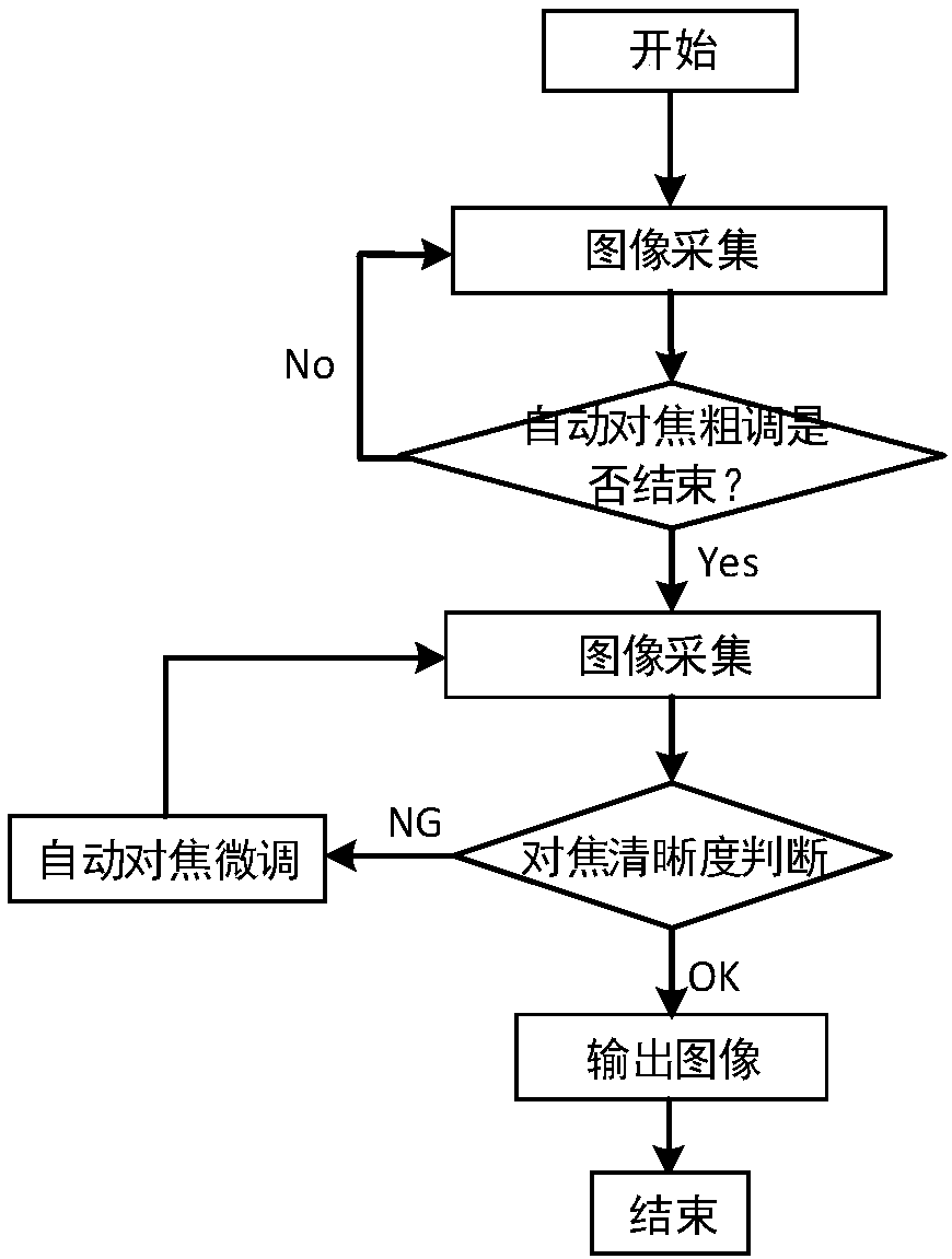
[0042] refer to figure 1 , the fast autofocus method based on the display panel provided by the embodiment includes the following steps:

[0043] (1) Image collection: collect the image of the focus screen of the display panel;

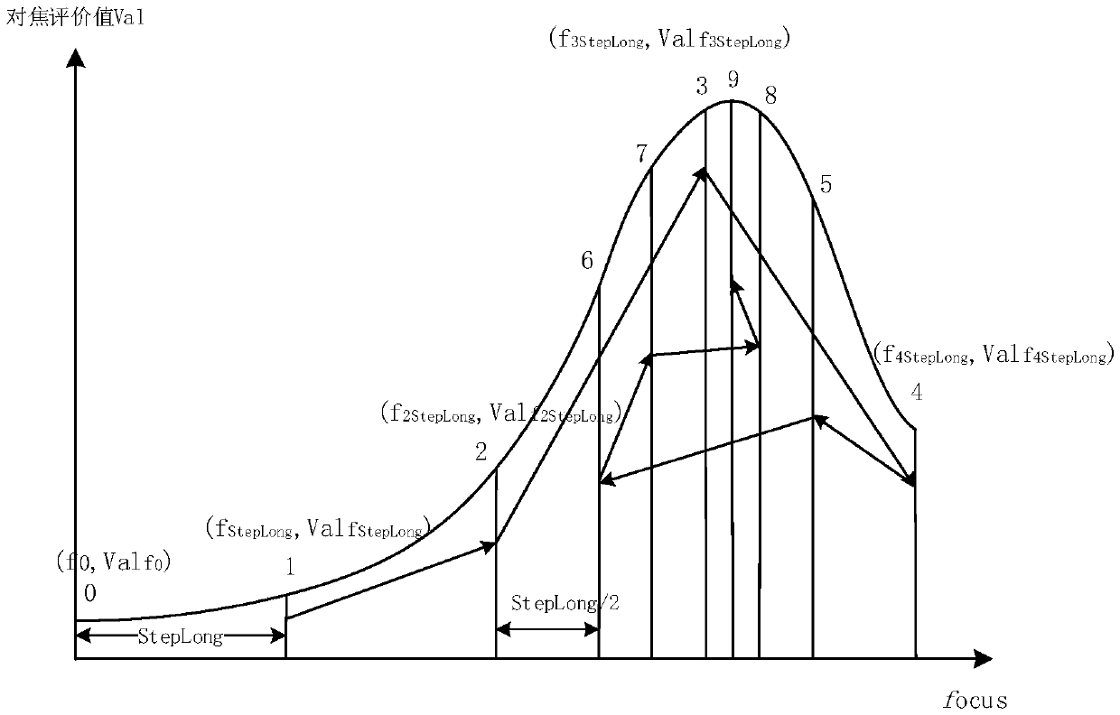
[0044] (2) Coarse autofocus adjustment: The dichotomy method is used to adjust the focus within the entire focal range, and the focus range with a clear image is determ...


PUM


Abstract

The invention belongs to the technical field of display panel defect detection, and discloses a fast auto-focusing method based on a display panel. The method includes the following steps: a focusingscreen image of a display panel is collected, focusing is carried out by dichotomy in the full focal range, the clear focusing range of the image is determined by long-step focusing, and the clear focusing position is determined in the focusing range by short-step focusing; an image corresponding to the clear focusing position is collected at the clear focusing position, and the focusing clarity is judged; if the focusing clarity satisfies a preset threshold requirement, the image is output; and otherwise, an image is collected and the focusing clarity is judged again after auto-focusing fine-tuning until the focusing clarity satisfies the preset threshold requirement, and the image is output. According to the auto-focusing method provided by the invention, the clear focusing position is calculated through coarse focusing, and fine-tuning is carried out according to the clarity of the image at the focusing position. Therefore, the focusing accuracy is improved, error focusing is prevented, the accuracy of defect detection is improved, and the detection time is shortened.

Description

technical field [0001] The invention belongs to the technical field of display panel defect detection, and more specifically relates to a fast autofocus method based on a display panel. Background technique [0002] Image acquisition is a key part of the visual inspection of the display panel. In order to obtain a clear image during the acquisition process, the selection of the camera (resolution greater than the resolution of the display panel within the field of view) is the basis, and the adjustment of the focal length of the lens is also crucial. Manual focusing requires specialized personnel to perform repeated manual operations to judge the sharpness of the image, which is subjective and is easily affected by the environment and individuals. In some working conditions, manual operation will be very difficult and the efficiency is extremely high. Low. The traditional auto-focus method, based on distance measurement or phase shift, has high cost, large error, and high e...

Claims


Application Information

Patent Timeline
IPC IPC(8): G03B13/36G02B7/28H04N5/232
CPCG02B7/285G03B13/36H04N23/67
Inventor 余梦露花华妹马尔威郑增强
Owner WUHAN JINGLI ELECTRONICS TECH
Learn More