
a grinding device

A technology of grinder and machine base, which is applied in the direction of grinding machines, spherical grinders, grinding workpiece supports, etc., and can solve problems such as time-consuming and laborious, uneven grinding effects, and affecting visual effects

Active Publication Date: 2021-03-19
青岛泰富科技有限公司
View PDF8 Cites 0 Cited by
  • Summary
  • Abstract
  • Description
  • Claims
  • Application Information

AI Technical Summary

Problems solved by technology

[0002] Chain beads are composed of a plurality of balls and a thread belt passing through the center hole of each ball. The existing chain-bead jewelry, jade, precious metal balls and other valuables need to be polished on the surface, so that they can be cleaned. For further maintenance, traditionally, manual polishing is used, which is time-consuming and laborious
[0003] There are also some electric grinding equipment on the market, which saves time, effort, and time. However, most machines only drive the chain beads in one direction or in the forward and reverse directions during the grinding process of the chain beads. , since the balls cannot be driven to rotate while driving the chain beads, only part of the surface of the chain beads can be polished, resulting in uneven final grinding effect and affecting the visual effect

Method used


Image

  • a grinding device
  • a grinding device
  • a grinding device

Examples


Embodiment 1

[0015] (embodiment 1, box type grinder)

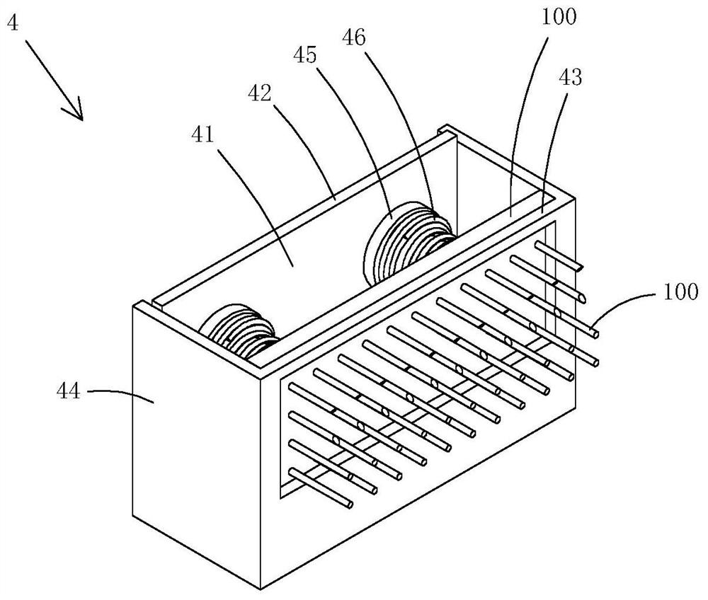
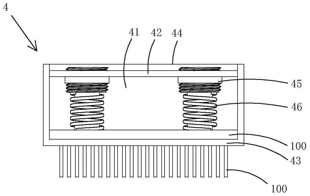
[0016] This embodiment is a box sander, see Figure 1 to Figure 2 As shown, the box type grinder 4 includes a box body 44 provided with a sliding cavity 41, a positioning plate 42 and a baffle plate 43, a scrub brush 100 slidably arranged in the sliding cavity, an adjusting bolt 45 arranged on the positioning plate is rotated, and Compression spring 46; one end of the compression spring abuts on the adjusting bolt, the other end abuts on the plate brush, and presses the plate brush to the baffle plate. Rotating the adjusting bolt can adjust the length of the adjusting bolt protruding into the sliding cavity, thereby adjusting the stress of the compression spring.

[0017] In this embodiment, the size of the workpiece can be ground adaptively, and an adaptive grinding pressure can be applied thereto.

Embodiment 2

[0018] (embodiment 2, grinding device)

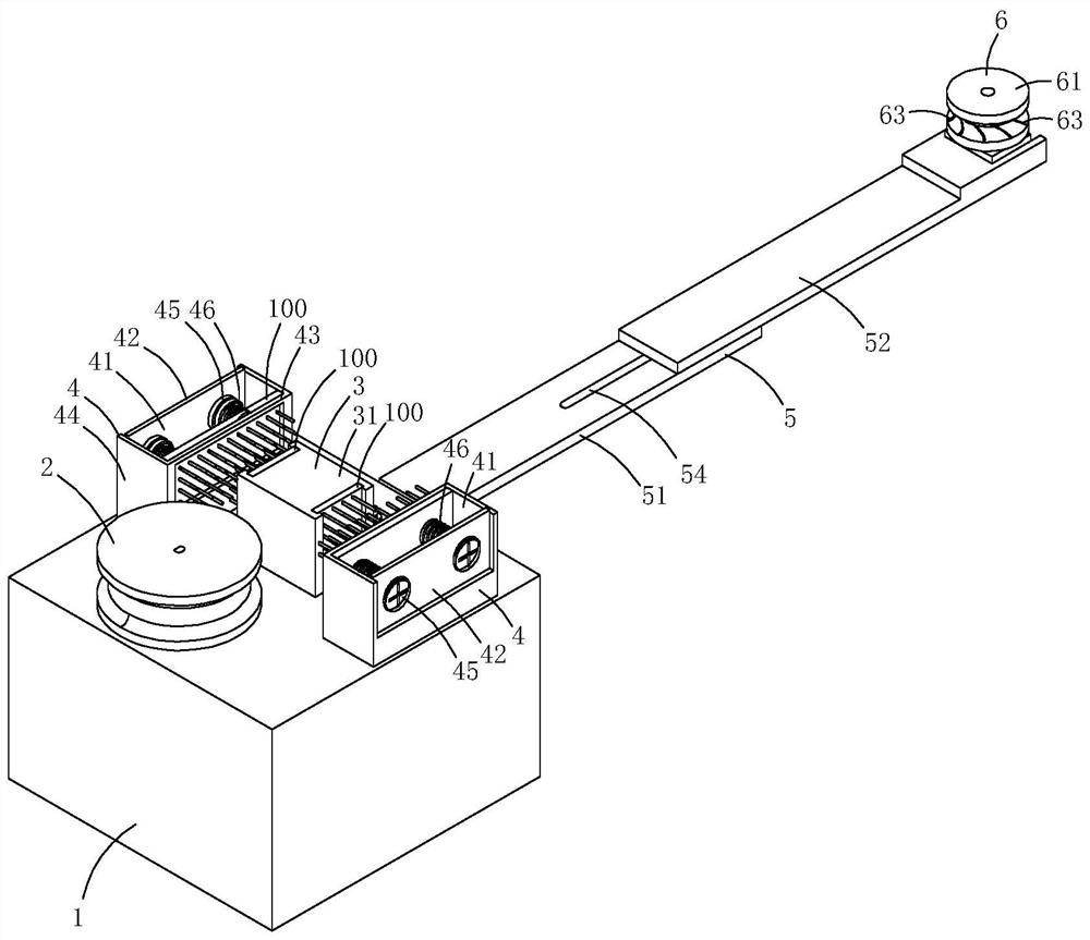
[0019] This embodiment is a kind of chain bead grinding device made by adopting the above-mentioned embodiment 1, see Figure 3 to Figure 7 As shown, it includes a machine base 1, a drive wheel 2 arranged on the top wall of the machine base, a double-headed grinder 3 and a box-type grinder 4, and the drive wheel drive mechanism arranged inside the machine base is arranged on the side wall of the machine base. The combined support plate 5, and the rotary wheel 6 and the rotary wheel driving mechanism 7 arranged on the combined support plate.

[0020] The double-head sander includes a housing 31 fixed on the top wall of the machine base and two scrub brushes 100 arranged on opposite sides of the housing. The housing is provided with slots, and the scrub brushes 100 are plugged into the slots.

[0021] The box sander comprises a box body 44 provided with a slide chamber 41, a positioning plate 42 and a baffle plate 43, a scrub brush 100 a...


PUM


Abstract

The invention discloses a box type sanding device. The box type sanding device comprises a box body provided with a sliding cavity, a positioning plate and a baffle, a plate brush, an adjusting bolt rotationally arranged on the positioning plate, and a compression spring; one end of the compression spring abuts against the adjusting bolt, the other end of the compression spring abuts against the plate brush and presses the plate brush onto the baffle; and the plate brush is slidably arranged in the sliding cavity. The box type sanding device has the advantage that the box type sanding device automatically adapts to the dimensions of sanded workpieces and applies self-adaptive sanding pressure to the sanded workpieces.

Description

technical field [0001] The invention relates to a grinding device. Background technique [0002] Chain beads are composed of a plurality of balls and a thread belt passing through the center hole of each ball. The existing chain-bead jewelry, jade, precious metal balls and other valuables need to be polished on the surface, so that they can be cleaned. For further maintenance, traditionally, manual polishing is used, which is time-consuming and laborious. [0003] There are also some electric grinding equipment on the market, which saves time, effort, and time. However, most machines only drive the chain beads in one direction or in the forward and reverse directions during the grinding process of the chain beads. , since the balls cannot be driven to rotate while driving the chain beads, only part of the surface of the chain beads can be polished, resulting in uneven grinding effect and affecting the visual effect. Contents of the invention [0004] The purpose of the p...

Claims


Application Information

Patent Timeline
Patent Type & Authority Patents(China)
IPC IPC(8): B24B27/00B24B11/02B24B41/00B24B41/06
Inventor 管伟
Owner 青岛泰富科技有限公司
Learn More