
Guide bar drives and guide bar assemblies for warp knitting machines

A technology of guide bar and driving device, which is applied in warp knitting, textiles, papermaking, knitting, etc., and can solve the problems of high mechanical cost and other problems

Active Publication Date: 2020-07-28
KARL MAYER STOLL R&D GMBH
View PDF9 Cites 0 Cited by
  • Summary
  • Abstract
  • Description
  • Claims
  • Application Information

AI Technical Summary

Problems solved by technology

However, the mechanical complexity is relatively high when using a transmission with threaded spindle and spherical nut

Method used


Image

  • Guide bar drives and guide bar assemblies for warp knitting machines
  • Guide bar drives and guide bar assemblies for warp knitting machines
  • Guide bar drives and guide bar assemblies for warp knitting machines

Examples


Embodiment Construction

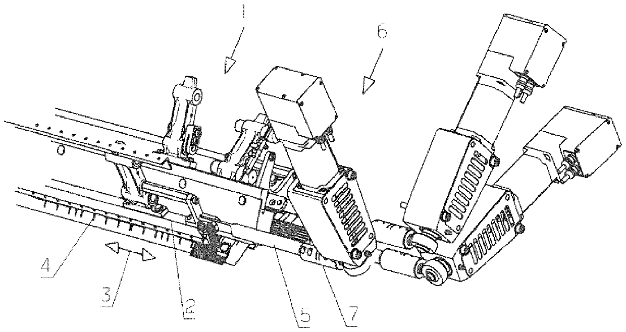
[0030] The thread guide bar assembly 1 has a plurality of thread guide bars 2 which are to be moved back and forth in the offset direction represented by the double arrow 3 . Each thread guide bar 2 carries a certain number of thread guides 4 which can be designed, for example, as thread guide needles or eyelets.

[0031] Each yarn guide bar is connected with the yarn guide bar driving device 6 via a driving push rod 5 . exist figure 1 In the embodiment of the present invention, the drive push rod 5 has a length adjustment device 7, and the length of the drive push rod 5 can be adjusted to a certain limit with the difference between the yarn guide bar 2 and the yarn guide bar drive device 6 by using the length adjustment device 7. The spacing in the neutral position of the two elements matches.

[0032] However, it is advantageous if the length adjustment device 7 is arranged in the region of the thread guide bar 2 and is preferably connected to the thread guide bar 2 . Bas...


PUM


Abstract

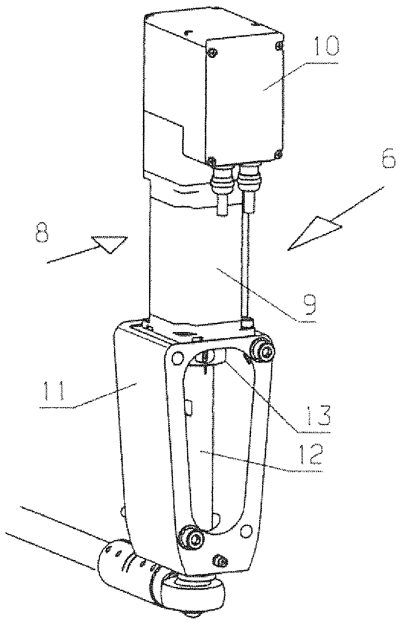
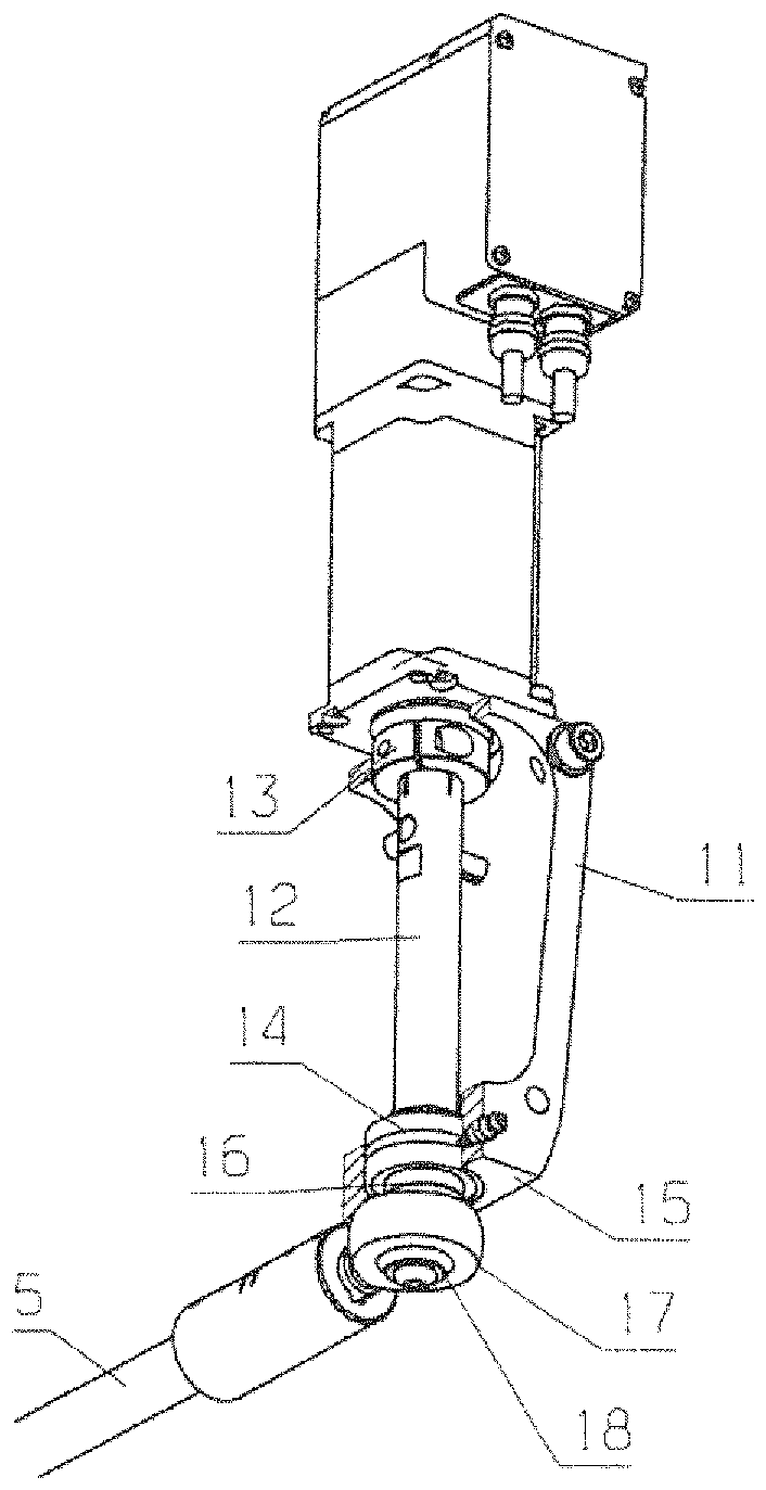
The present invention relates to a yarn guide bar driving device and a yarn guide bar assembly of a warp knitting machine, specifically, a yarn guide bar driving device (6) of a warp knitting machine is provided with a motor assembly (8), The motor assembly (8) has a rotationally driven drive element (12), which has an axis of rotation and which cooperates with a drive plunger (5). It would be desirable to be able to independently actuate a thread guide bar in the deflection direction with little effort. For this purpose, it is provided that the effective connection between the drive element (12) and the drive tappet (5) is arranged eccentrically to the axis of rotation.

Description

technical field [0001] The invention relates to a guide bar drive of a warp knitting machine with a motor assembly having a rotationally driven drive element having an axis of rotation and cooperating with a drive push rod . [0002] Furthermore, the invention relates to a thread guide bar assembly with at least one thread guide bar and such a drive. Background technique [0003] During operation of the warp knitting machine, the guide needles guiding the yarns of the yarn sheets (Fadenschar) must be guided relative to the working needles (Arbeitnadel) or knitting needles (Wirknadel) so that the yarns of the yarn sheets can form loops (Maschen) . For this purpose, the thread guide bar must be moved in the so-called offset direction, ie parallel to its longitudinal extension. This offset movement is brought about by the thread guide bar drive. [0004] Over the past few years there has been an increasing shift towards direct drive of the yarn guide bars via motor assembli...

Claims


Application Information

Patent Timeline
Patent Type & Authority Patents(China)
IPC IPC(8): D04B27/24
CPCD04B27/26D04B37/06
Inventor M.鲁G.克劳斯
Owner KARL MAYER STOLL R&D GMBH
Learn More