
A bearing directional air cooling device

An air cooling and bearing technology, applied in the field of bearing cooling, can solve the problems of large cooling area, inability to solve local heat energy concentration, affect bearing service life and product performance, and achieve the effect of solving local heat concentration

Active Publication Date: 2021-07-09
GUANGZHOU HAOZHI ELECTROMECHANICAL
View PDF5 Cites 0 Cited by
  • Summary
  • Abstract
  • Description
  • Claims
  • Application Information

AI Technical Summary

Problems solved by technology

If the heat energy cannot be dissipated in time, it will affect the service life of the bearing and product performance
[0003] The commonly used method is to design a water-cooled or air-cooled structure on the body or bearing seat to realize the indirect cooling of the bearing. This method has a large cooling area, but its efficiency is low and it cannot solve the current situation of local concentration of heat energy on the bearing.

Method used


Image

  • A bearing directional air cooling device
  • A bearing directional air cooling device

Examples


Embodiment Construction

[0021] Below, the present invention will be further described in conjunction with the accompanying drawings and specific implementation methods. It should be noted that, under the premise of not conflicting, the various embodiments described below or the technical features can be combined arbitrarily to form new embodiments. .

[0022] In describing the present invention, it is to be understood that the terms "upper", "lower", "front", "rear", "left", "right", "horizontal", "vertical", "top", The orientation or positional relationship indicated by "inner", "outer", etc. is based on the orientation or positional relationship shown in the drawings, and is only for the convenience of describing the present invention and simplifying the description, rather than indicating or implying that the referred device or element must have Certain orientations, constructed and operative in certain orientations, therefore are not to be construed as limitations of the invention. In addition, ...


PUM


Abstract

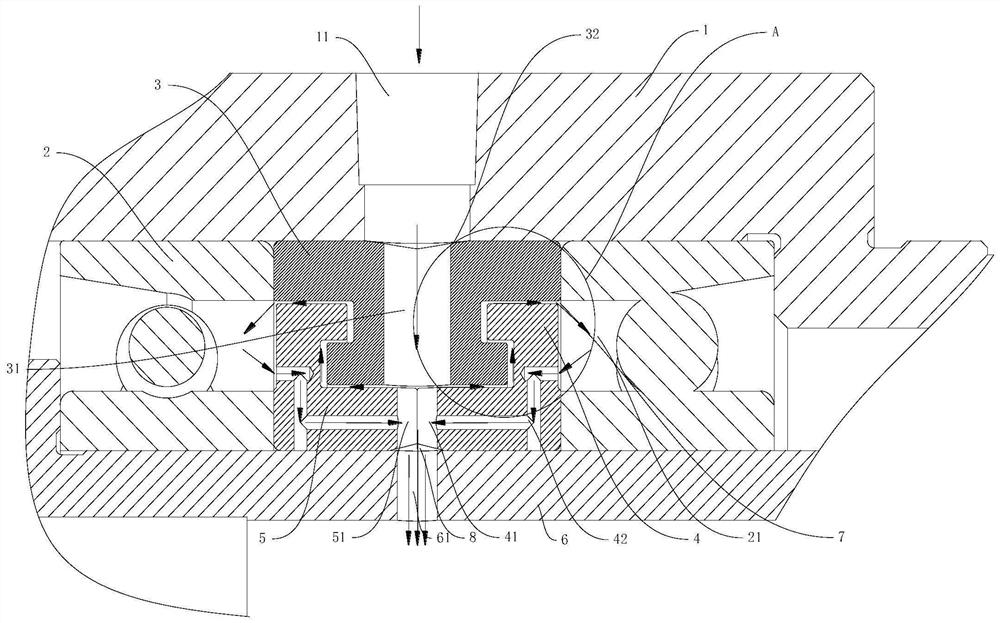
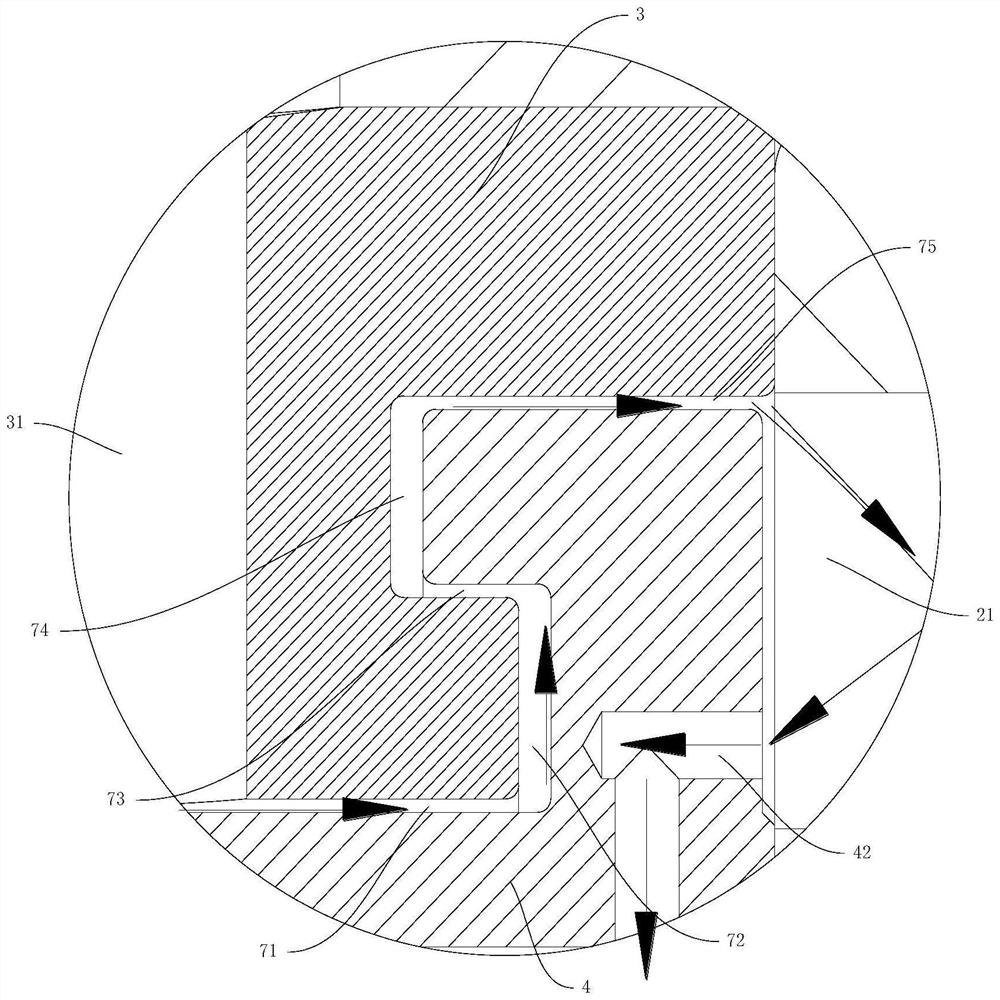
The invention discloses a bearing directional air cooling device, which comprises a bearing seat, a bearing, a spacer and a rotating shaft, the inner ring of the bearing cooperates with the rotating shaft, the outer ring of the bearing cooperates with the inner hole of the bearing seat, two bearings are arranged, and the spacer Sleeved between the two bearings, it also has a ventilation channel, a cooling channel and a ventilation circuit. The ventilation channel connects the bearing seat, the spacer and the center hole of the rotating shaft in turn. The entrance of the ventilation channel is used to communicate with the external air supply system. Cooling The channel is arranged in the spacer, the inlet of the cooling channel communicates with the ventilation channel, the outlet of the cooling channel communicates with the inside of the bearing, the inlet of the ventilation circuit communicates with the inside of the bearing, and the outlet of the ventilation circuit communicates with the ventilation channel. The bearing directional air cooling device can input cooling air to the position of the bearing and the bearing spacer, so as to realize the direct cooling of the inner structure of the bearing.

Description

technical field [0001] The invention relates to the technical field of bearing cooling, in particular to a bearing directional air cooling device. Background technique [0002] The bearing is the core component to ensure the high-precision and high-speed operation of the spindle, and because of the high speed, the bearing generates a lot of heat during work. If the heat energy cannot be dissipated in time, it will affect the service life of the bearing and product performance. [0003] The commonly used method is to design a water-cooled or air-cooled structure on the body or bearing housing to achieve indirect cooling of the bearing. This method has a large cooling area, but its efficiency is low and it cannot solve the current situation of local concentration of heat energy on the bearing. Contents of the invention [0004] In order to overcome the deficiencies of the prior art, the purpose of the present invention is to provide a bearing directional air cooling device,...

Claims


Application Information

Patent Timeline
Patent Type & Authority Patents(China)
IPC IPC(8): F16C35/04F16C37/00F16C33/58F16C33/80
Inventor 张世洋谌均熠卢云飞明希军汤秀清
Owner GUANGZHOU HAOZHI ELECTROMECHANICAL
Learn More