
Suspension type microgravity simulation device and control method

A simulation device and suspended micro technology, which is applied to the simulation device of space navigation conditions, transportation and packaging, space navigation equipment, etc., can solve the problems of small follow-up deviation, damage to the microgravity simulation mechanical environment, etc., to ensure authenticity Effect

Active Publication Date: 2019-05-07
HARBIN INST OF TECH
View PDF6 Cites 12 Cited by
  • Summary
  • Abstract
  • Description
  • Claims
  • Application Information

AI Technical Summary

Problems solved by technology

[0004] The present invention provides a suspended microgravity simulation device and an The control method is to build a follow-up control system for microgravity environment simulation in the form of visual servoing, combined with a stable control strategy, to ensure high simulation accuracy during the working process of the suspended microgravity simulation device. The specific technical solution to this problem is as follows:

Method used


Image

  • Suspension type microgravity simulation device and control method
  • Suspension type microgravity simulation device and control method
  • Suspension type microgravity simulation device and control method

Examples


specific Embodiment approach 1

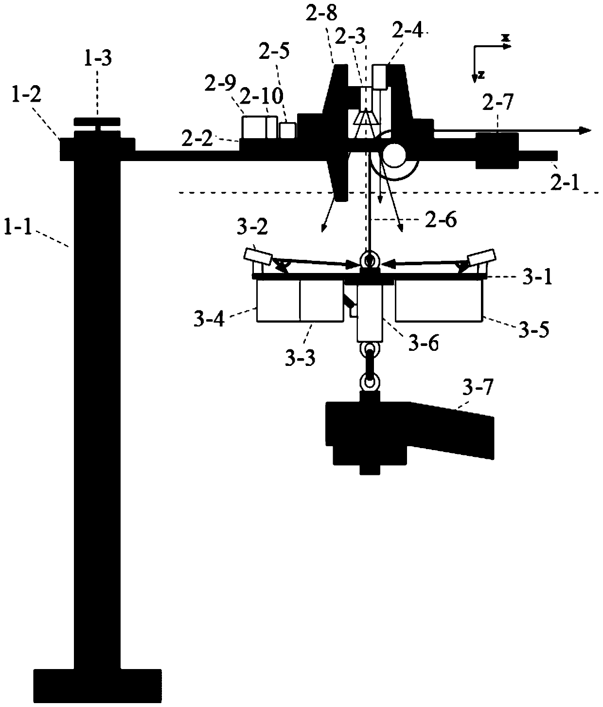
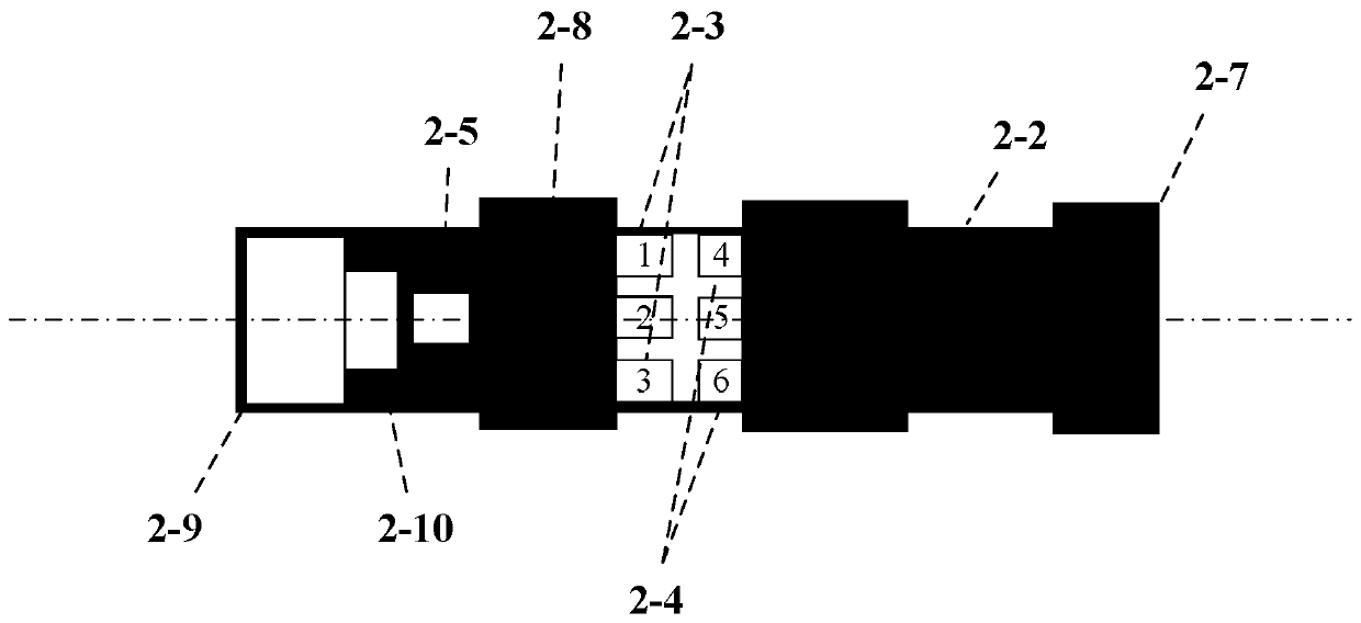
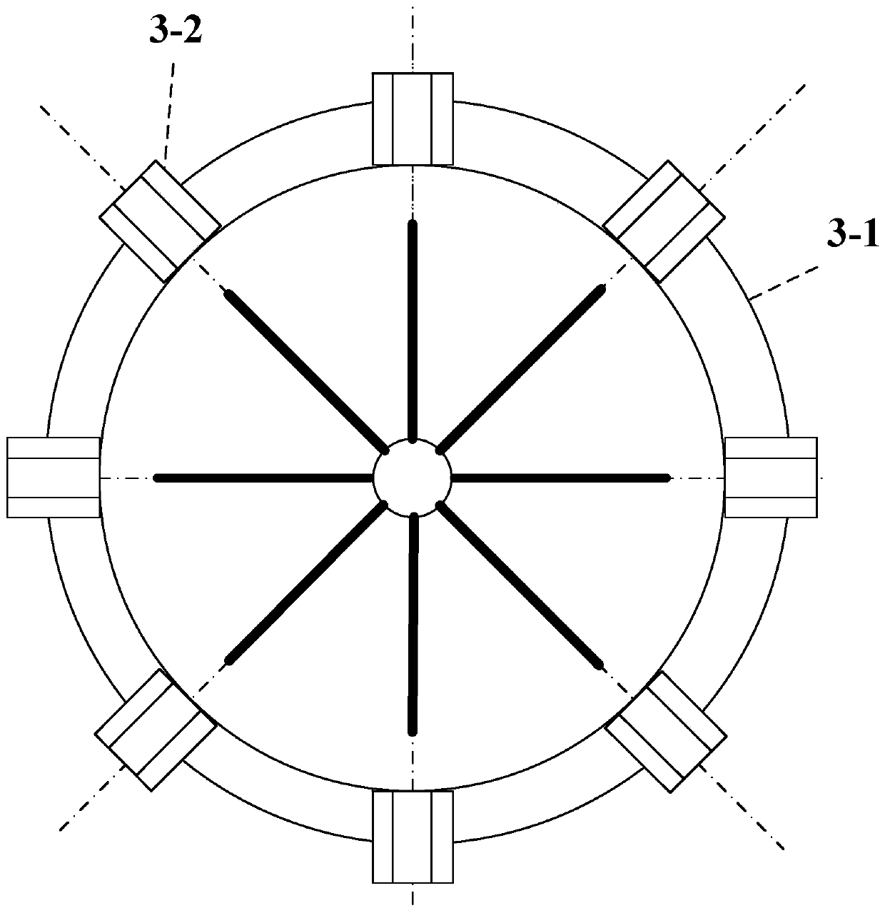
[0013] Specific implementation mode one: combine figure 1 , figure 2 , image 3 and Figure 4 The present embodiment will be described. The device of this embodiment is composed of a support rotation module 1, an arm module 2 and a lifting point module 3, the support rotation module is connected with the arm module 2, and the slings 2-6 in the arm module 2 are connected Lightweight aluminum disc 3-1 connection;

[0014] Described support rotation module is made up of support column 1-1, rotating arm driving motor 1-2 and inclination measuring instrument 1-3, and rotating arm driving motor 1-2 is arranged on the top of supporting column 1-1, and inclination measuring instrument 1 -3 is arranged on the upper end of the supporting column 1-1, the driving motor 1-2 of the rotating arm is connected with the guide rail platform 2-1 of the module on the arm,

[0015] The above-arm module is composed of a guide rail platform 2-1, a translation vehicle 2-2, a visual sensor 2-3, a...

specific Embodiment approach 2

[0017] Specific implementation mode two: combination figure 1 and figure 2 The present embodiment will be described. 25mm and 50mm cameras 2-3 and two laser range finders 2-4 of the same model are respectively arranged on the translation vehicle 2-2 described in this embodiment.

specific Embodiment approach 3

[0018] Specific implementation mode three: combination figure 1 and figure 2 The present embodiment will be described. The camera described in this embodiment adopts a 3.69um pixel of 30mm. The measurement error is less than 0.5mm, the typical value is 0.1-0.3mm, the pixel resolution is 1mm, and the linear fitting sub-pixel resolution can reach 0.5mm.


PUM

PropertyMeasurementUnit
Widthaaaaaaaaaa
Lengthaaaaaaaaaa

Abstract

The invention discloses a suspension type microgravity simulation device and a control method, and relates to visual pose measurement. The suspension type microgravity simulation device and the control method solve the problem that the follower deviation causes a suspension wire to generate disturbance torque in the horizontal direction resulting in damage to the mechanical environment of microgravity simulation. The device disclosed by the invention consists of a supporting rotation module, an on-arm module and a suspension point module, wherein the supporting rotation module is connected tothe on-arm module; and a suspension cable in the on-arm module is connected to a lightweight aluminum plate in the suspension point module. The method calculates position and speed control parametersof rotation and translation by taking the position offset of the suspension point, the inclination angle of the suspension wire and the tension of the suspension wire as inputs, and performs real-timefeedback on the position and speed so as to achieve radial and rotational tracking of the suspension point. The suspension type microgravity simulation device and the control method ensure the advantages of authenticity, stability and reliability of the ground simulation of space missions.

Description

technical field [0001] The invention relates to a visual pose measurement device and method, in particular to a suspended microgravity simulation device and a control method. Background technique [0002] At present, in order to ensure the reliability of space missions, a large number of experiments need to be carried out before the execution of space missions. Among them, as one of the important characteristics of space, microgravity operation needs to be fully tested and verified. It is currently the most economical and effective method to establish a space microgravity environment simulation platform on the ground to carry out space mission experiment research. [0003] At present, a variety of methods can be used for space microgravity ground simulation tests, including drop tower method, water flotation method, air flotation method and suspension method. As a relatively simple and easy-to-implement method, the suspension method is widely used in many microgravity simul...

Claims


Application Information

Patent Timeline
IPC IPC(8): B64G7/00
Inventor 金野刘鹏朱海龙刘家锋赵巍唐降龙
Owner HARBIN INST OF TECH
Learn More