A drilling rig actuator and a bolter rig

A technology for actuators and rock bolters, which can be used in the installation of rock bolts, rotary drilling rigs, directional drilling, etc., and can solve the problem of low positioning efficiency

Active Publication Date: 2020-05-15
江苏中贵重工有限公司
View PDF14 Cites 1 Cited by
  • Summary
  • Abstract
  • Description
  • Claims
  • Application Information

AI Technical Summary

Problems solved by technology

[0003] The embodiment of the present application provides a drill rig actuator and a bolter rig to improve the problem of low positioning efficiency during drilling operations

Method used


Image

  • A drilling rig actuator and a bolter rig
  • A drilling rig actuator and a bolter rig
  • A drilling rig actuator and a bolter rig

Examples


Embodiment 1

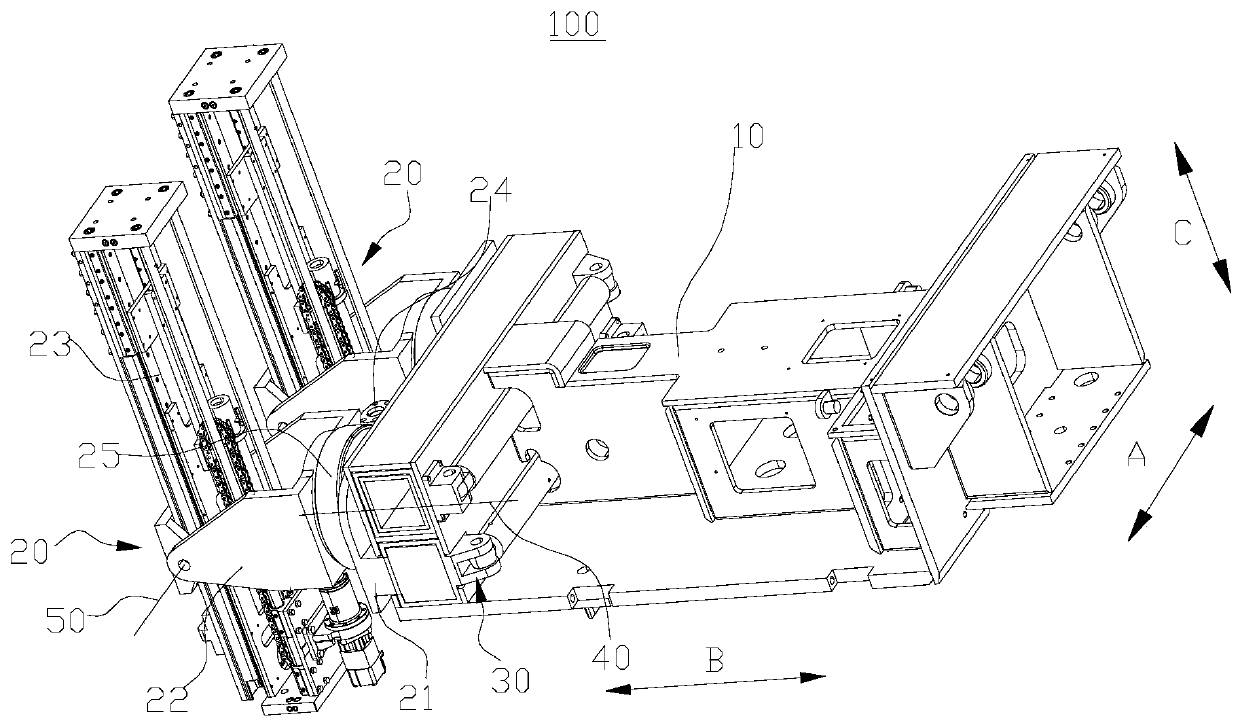
[0072] Such as figure 1 As shown, this embodiment provides a drilling rig actuator 100 , including a base 10 , an actuator 20 and a driving mechanism 30 .

[0073] The base body 10 is configured to be compatible with the running gear ( figure 1 not shown), the running gear has a transverse direction A, a longitudinal direction B and a vertical direction C, and the walking direction of the walking gear is the longitudinal direction B.

[0074] Understandably, when the walking device is placed on a horizontal plane, the horizontal direction A and the longitudinal direction B are two directions perpendicular to each other in the horizontal plane, and the vertical direction C is the direction perpendicular to the horizontal plane. Of course, the drilling rig actuator 100 also has a transverse direction A, a longitudinal direction B, and a vertical direction C. After the base body 10 of the drilling rig actuator 100 is connected to the traveling device, the transverse direction A ...

Embodiment 2

[0106] Such as Figure 10 As shown, this embodiment provides a rock bolter 200 , including a running device 210 and the drilling rig actuator 100 in the above embodiment, and the base body 10 is connected to the running device 210 .

[0107] Optionally, the running device 210 includes a chassis 211 and a crawler running mechanism 212 disposed at the bottom of the chassis 211 , and the running device 210 is realized by the crawler running mechanism 212 .

[0108] The walking device 210 has a transverse direction A, a longitudinal direction B and a vertical direction C, and the walking direction of the traveling device 210 is the longitudinal direction B.

[0109] Understandably, when the walking device 210 is placed in a horizontal plane, the horizontal direction A and the longitudinal direction B are two directions perpendicular to each other in the horizontal plane, and the vertical direction C is a direction perpendicular to the horizontal plane. The horizontal direction A ...


PUM


Abstract

The invention provides a drill carriage actuator and an anchor rod drill carriage, and belongs to the technical field of drill carriages. The drill carriage actuator comprises a base body, an actuation device and a driving mechanism, wherein the base body is configured to be connected with a walking device; the actuation device comprises a connecting base, a rotating base, a power head, a first driving device and a second driving device. The rotating base is rotationally arranged on the connecting base, the first driving device is configured to drive the rotating base to rotate around a firstaxis relative to the connecting base; the power head is rotationally arranged on the rotating base; the second driving device is configured to drive the power head to rotate around a second axis relative to the rotating base. The connecting base is in transmission connection with the base body through the driving mechanism which is configured to drive the actuation device to transversely move relative to the base body. The first axis is in the longitudinal direction or longitudinally arranged, and the second axis is in the transverse direction or transversely arranged. When the transverse position of the power head is adjusted, it is only required the driving mechanism works without adjusting the position of the power head through movement of the walking device, and the positioning efficiency is high.

Description

technical field [0001] The present application relates to the technical field of drilling rigs, in particular, to a drilling rig actuator and a rock bolter rig. Background technique [0002] At present, the rock bolter is a mobile device used to drill anchor holes. It includes a traveling device and a drilling rig actuator. The drilling rig actuator includes a mechanical arm and a power head. The power head is connected to the walking device through the mechanical arm. Each joint of the arm can only move in the same vertical plane. When drilling and positioning, it is necessary to realize the lateral movement of the power head through the movement of the walking device, and the positioning efficiency is low. Contents of the invention [0003] Embodiments of the present application provide a drill rig actuator and a rod bolter rig to improve the problem of low positioning efficiency during drilling operations. [0004] In the first aspect, the embodiment of the present app...

Claims


Application Information

Patent Timeline
Patent Type & Authority Patents(China)
IPC IPC(8): E21B7/02E21B7/04E21B3/02E21B15/04E21D20/00
Inventor 李钦彬崔治司癸卯任军王兴文李帅
Owner 江苏中贵重工有限公司
Why Eureka
Try Eureka