A sound source control valve for an automatic liquid level measurement device for high-pressure gas wells

An automatic measurement and high-pressure gas technology, which is applied in the direction of valve devices, valve lifts, engine components, etc., can solve problems such as sound source control valve failure, high electromagnetic suction, and sound source control valve failure to trigger, so as to solve the problems of failure to reset and reduce Effect of Spring Preload Requirements

Active Publication Date: 2020-07-14
贵州航天凯山石油仪器有限公司
View PDF7 Cites 0 Cited by
  • Summary
  • Abstract
  • Description
  • Claims
  • Application Information

AI Technical Summary

Problems solved by technology

At this time, the cross-sectional area of ​​the valve stem assembly is larger than the pressure balance cross-sectional area. After firing, the valve stem assembly needs to overcome the pressure P to reset the pressure generated by the cross-section of the valve stem assembly. The greater the pressure, the greater the reset force required. When the maximum pre-tightening force can be provided, the valve stem cannot be reset, resulting in the failure of the sound source control valve;
[0006] c) Affected by the size of the instrument and energy consumption, the electromagnetic attraction force of the electromagnet of the sound source control valve is constant. If the pressure balance cross section of the sound source control valve is equal to the cross section of the valve stem assembly, the pressure balance cross section is larger than the valve port As the pressure in the well increases, the electromagnetic suction required for the firing of the sound source control valve becomes larger and larger. When the maximum suction force provided by the electromagnet is exceeded, the sound source control valve cannot be fired.

Method used


Image

  • A sound source control valve for an automatic liquid level measurement device for high-pressure gas wells
  • A sound source control valve for an automatic liquid level measurement device for high-pressure gas wells
  • A sound source control valve for an automatic liquid level measurement device for high-pressure gas wells

Examples


Embodiment 1

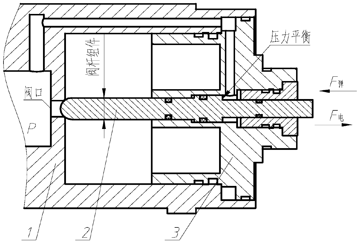
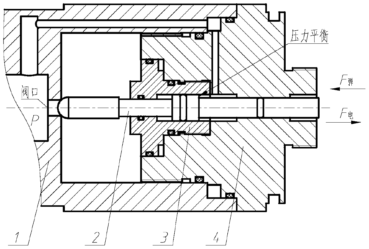
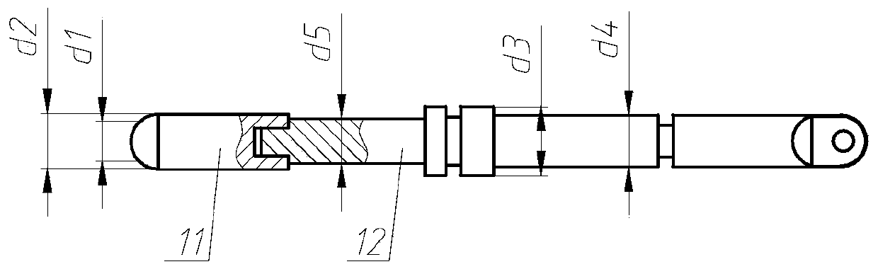
[0026] see figure 2 , the valve stem assembly 2 of the present invention is as image 3 As shown, it is composed of a valve core 11 and a valve stem 12. In order to ensure the coaxiality of the valve stem assembly 2, the valve core 11 and the valve stem 12 adopt an interference fit. The sound source control valve adopts a pressure balance design, and the pressure balance channel is composed of the valve body 1 and the end cover 4, so that the cross section of the valve stem assembly 2 and the valve port receive the same pressure to balance the pressure. Valve port when stem assembly 2 is closed area, stem the area of The areas of the circles are completely equal, and the valve stem assembly 2 is always in a state of pressure balance no matter when it is opened or when it is closed.

[0027] In the present invention, the force of the valve stem assembly of the sound source control valve is a constant high-pressure test requirement; the requirement for the electromagn...


PUM


Abstract

The invention discloses a sound source control valve for an automatic high-pressure gas well liquid level measuring device. The sound source control valve comprises a valve body (1), a valve rod assembly (2), a plug (3) and an end cover (4). The valve body (1) is provided with a valve port, the plug (3) and the end cover (4) are provided with through holes and the valve port and the through holesare coaxial; the valve body assembly (2) penetrate the through holes of the plug (3) and the end cover (4), and one end of the valve body assembly (2) plugs the valve port of the valve body (1). In order to balance the pressure of the sound source control valve, the valve port of the valve body (1) and the through holes of the plug (3) and the end cover (4) form a pressure balancing channel, so that the pressures of the section of the valve rod assembly (2) and the valve body (1) at the valve port are equal. The sound source control valve solves the problem that the valve body assembly cannotbe percussed as the pressure is raised and also solves the problem that the valve rod assembly cannot be reset as the pressure is raised.

Description

technical field [0001] The invention belongs to the technical field of gas field well testing instruments, in particular to a sound source control valve for an automatic liquid level measurement device for measuring the liquid level depth of a high-pressure gas well. Background technique [0002] Since the gas well will have liquid accumulation during the production process, when the liquid accumulation is too high, the gas production will decrease, and even the gas well will be scrapped. In order to increase production and income, it is necessary to test the liquid level of the gas well in real time. The automatic measurement device for the liquid level depth of the high-pressure gas well is a device used in the gas field gas production process to generate and receive sound waves for the liquid level depth of the gas well. Through the reception and processing of the sound waves, it can Calculate the depth of the liquid surface of the gas well, and the mechanism that automat...

Claims


Application Information

Patent Timeline
Patent Type & Authority Patents(China)
IPC IPC(8): F16K1/00F16K1/32F16K1/48
Inventor 周文强
Owner 贵州航天凯山石油仪器有限公司
Why Eureka
Try Eureka