Fire cover and high-efficiency burner applying fire cover

A gas burner and fire cover technology, which is applied in the direction of burners, gas fuel burners, combustion methods, etc., can solve the problems of insufficient high-efficiency combustion, limited secondary air supply capacity, etc., to shorten the supply path and improve supply efficiency , the effect of improving combustion efficiency

Pending Publication Date: 2019-05-07
NINGBO FOTILE KITCHEN WARE CO LTD
View PDF0 Cites 2 Cited by
  • Summary
  • Abstract
  • Description
  • Claims
  • Application Information

AI Technical Summary

Problems solved by technology

However, in the existing burner structure as mentioned above, the supply capacity of secondary air is limited, which is far from meeting the needs of more efficient combustion (75%)

Method used


Image

  • Fire cover and high-efficiency burner applying fire cover
  • Fire cover and high-efficiency burner applying fire cover
  • Fire cover and high-efficiency burner applying fire cover

Examples


Embodiment 1

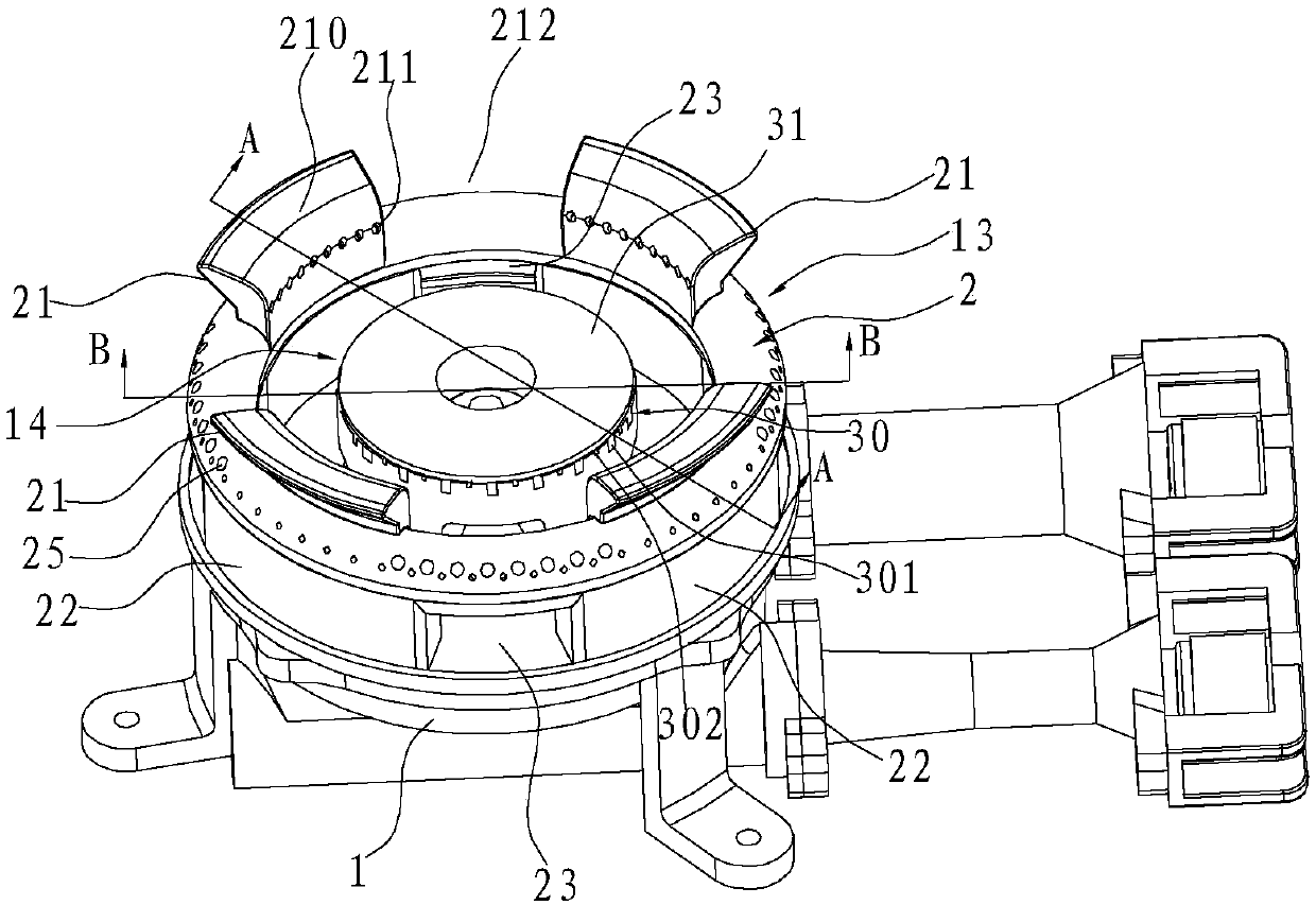
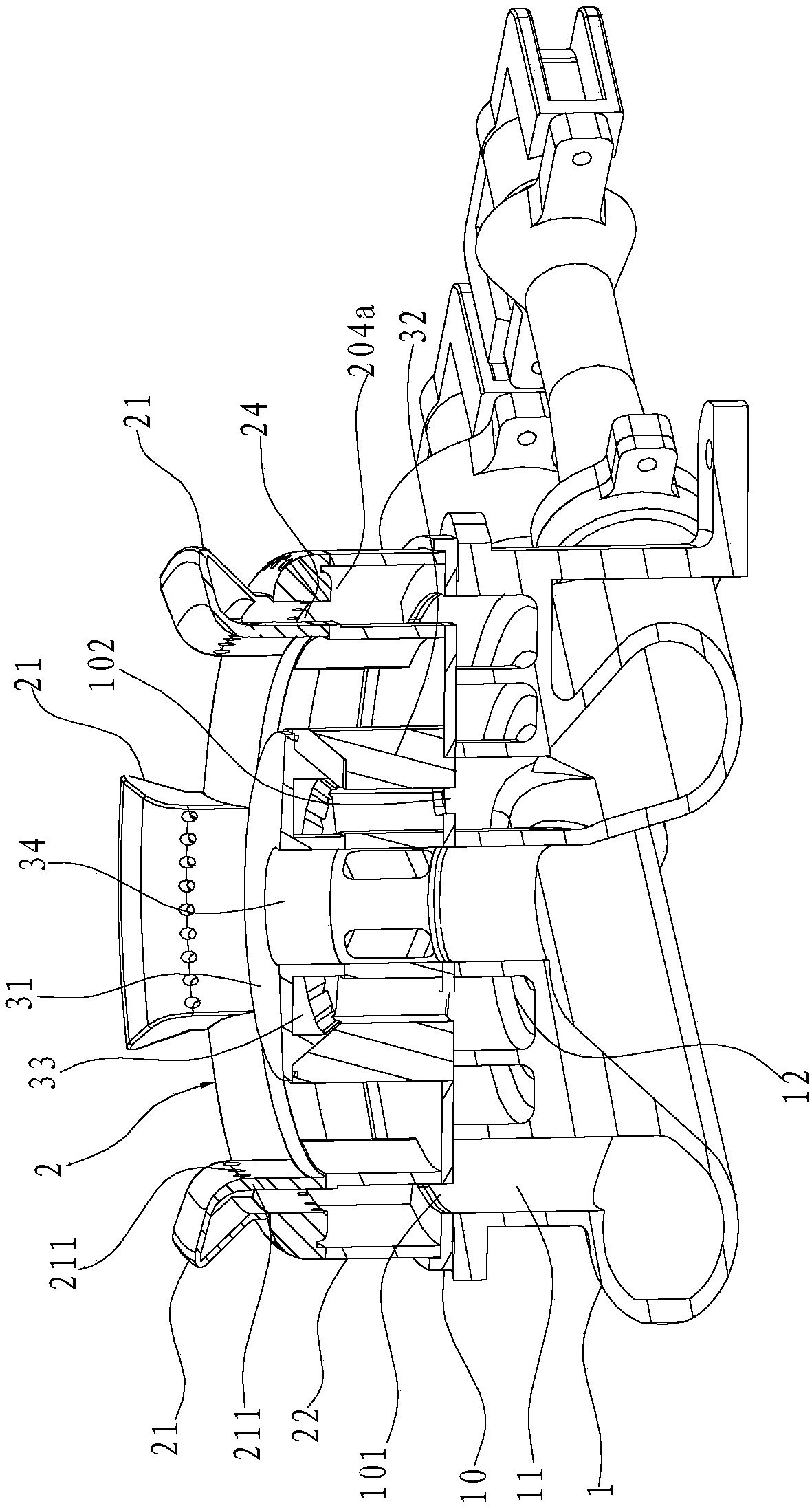
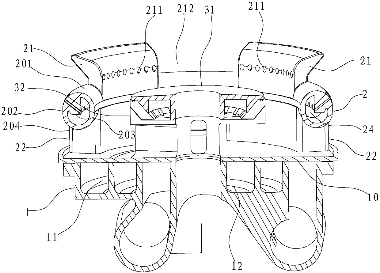
[0029] Such as Figure 1~6 As shown, a high-efficiency burner includes a base 1 and an outer ring fire cover 13 and an inner ring fire cover 14 arranged on the base 1 . Wherein the outer ring fire cover 13 comprises a ring-shaped first fire cover body 2, the first fire cover body 2 includes an annular top surface 201 and the inner edge and the outer edge of the annular top surface 201 are vertical or inclined downward. The extended inner ring wall 203 and the outer ring wall 202, the first air mixing chamber 24 is formed between the above-mentioned annular top surface 201, the inner ring wall 203 and the outer ring wall 202, and the above-mentioned outer ring wall 202 is arranged at intervals along the circumferential direction Main fire hole 25 is arranged.

[0030] Further, the lower edge of the outer ring wall 202 and the inner ring wall 203 are connected by the lower ring wall 204, and the lower ring wall 204 is provided with a plurality of air inlets 204a at intervals in...

Embodiment 2

[0039] Such as Figure 6 and 8 As shown, the difference from Embodiment 1 is that the inner ring fire cover 14 in this embodiment adopts a different structure from Embodiment 1. Specifically, the structure of the inner ring fire cover 14 in this embodiment is the same as that of the outer ring fire cover 13 in the first embodiment. In this way, the number of the inner ring vents 102 matches the number of the above-mentioned gas mixing tubes 22, and the free ends of each gas mixing tubes 22 are respectively connected to the corresponding inner ring vents 102, so that the outer ring cavity 11 passes through each The outer ring air vent 101 communicates with each gas mixing pipe 22 .


PUM


Abstract

The invention relates to a fire cover of a gas burner. The fire cover of the gas burner comprises an annular first fire cover body, wherein the first fire cover body comprises an annular top surface,and an inner ring wall and an outer ring wall extending vertically or inclinedly downwards from the inner side edge and the outer side edge of the annular top surface; a first gas mixing cavity is formed among the annular top surface, the inner ring wall and the outer ring wall; main fire holes are formed in the outer ring wall at intervals in the circumferential direction; and in the annular topsurface, the outer ring surface of the outer ring wall, and the outer ring surface of the inner ring wall, the outer ring surface of the outer ring wall is in a circular arc shape at least. The invention further relates to a high-efficiency burner applying the fire cover. Compared with the prior art, according to the fire cover and the high-efficiency burner applying the fire cover provided by theinvention, by utilizing a wall attachment effect, air tightly wraps the outer ring surface of the outer ring wall, so that a supply path of secondary air is shortened, and the secondary air can be more efficiently supplemented. Therefore, on the basis of an existing ejection system, through improving the fire cover, the secondary air supply efficiency can be effectively improved, so that the burning efficiency of the gas burner is improved.

Description

technical field [0001] The invention relates to the field of gas stoves, in particular to a fire cover and a high-efficiency burner using the fire cover. Background technique [0002] The gas burner includes a base, a gas mixing chamber, an outer ring fire cover and an inner ring fire cover, wherein the gas mixing chamber is set above the base, and the outer ring fire cover and the inner ring fire cover are respectively set above the gas mixing chamber . Among them, the outer ring fire cover is generally ring-shaped, including an annular top wall, an inner ring wall and an outer ring wall extending vertically downward or obliquely downward from the inner and outer sides of the annular top wall, and the annular top wall 1. The inner ring wall and the outer ring wall are surrounded to form a gas mixing chamber, and the outer ring wall is provided with an outer ring fire hole. The inner ring fire cover generally includes a cylindrical base and a cover body covering the base, ...

Claims


Application Information

Patent Timeline
Patent Type & Authority Applications(China)
IPC IPC(8): F23D14/58F23D14/02F23D14/62
Inventor 吴丽波王帅东茅忠群诸永定郑军妹
Owner NINGBO FOTILE KITCHEN WARE CO LTD
Why Eureka
Try Eureka