Pillar type ceramic insulator

A porcelain insulator and ceramic insulation technology, applied in the direction of supporting insulators, etc., can solve the problems of inability to adjust the size and use, inconvenient bolt fixing stability, etc., and achieve the effect of compact structure, convenient adjustment, and convenient use

Inactive Publication Date: 2019-05-07
萍乡市新田电瓷制造有限公司
View PDF0 Cites 2 Cited by
  • Summary
  • Abstract
  • Description
  • Claims
  • Application Information

AI Technical Summary

Problems solved by technology

[0004] The purpose of the present invention is to provide a pillar porcelain insulator with the ability to adapt to different sizes in order to solve the problems that the size of the groove on the top of the insulator used to pass through the wire cannot be adjusted, it is inconvenient to use and the stability is poor when only one bolt is used to fix it. The use of wires, the advantage of more stable installation

Method used


Image

  • Pillar type ceramic insulator
  • Pillar type ceramic insulator
  • Pillar type ceramic insulator

Examples


Embodiment 1

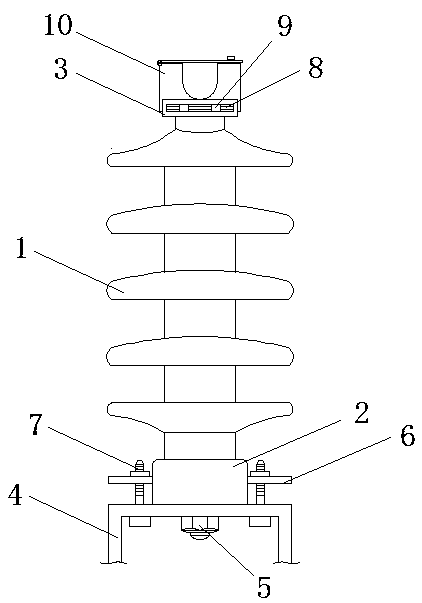
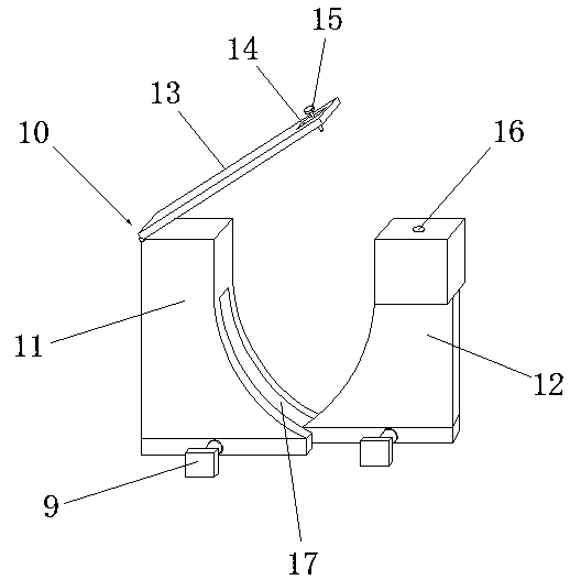
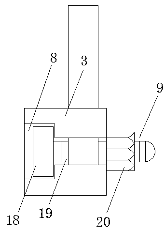
[0019] see Figure 1-2 As shown, a column type porcelain insulator includes a ceramic insulating core 1, a steel sleeve base 2 and a mounting frame 4, the bottom end of the ceramic insulating core 1 is installed with a steel sleeve base 2, the top end is equipped with a support top 3, and the top end of the support top 3 is installed Stringing mechanism 10; the mounting frame 4 is installed on the top of the high-voltage electric pole, and the bottom end of the steel sleeve base 2 is fixed on the top of the mounting frame 4 by the main bolt 5; the stringing mechanism 10 is composed of two mutually symmetrical first movable seats 11 and The second movable seat 12 is formed, and the opposite faces of the two movable seats are arc surfaces, the opposite side of the first movable seat 11 and the second movable seat 12 is provided with a slot 17, and the bottom end of the second movable seat 12 passes through the plug The bottom end of groove 17 and second movable seat 12 is plugge...

Embodiment 2

[0021] In addition, refer to Figure 1-3 , both sides of the outer wall of the steel sleeve base 2 are welded with connecting plates 6, and the connecting plates 6 are connected with the mounting frame 4 through positioning bolts 7, and the two positioning bolts 7 on the connecting plate 6 play the role of auxiliary fixing, sharing the main The pressure of the bolt 5 makes the installation of the ceramic insulating core 1 more stable. The top of the second movable seat 12 is provided with a screw hole 16, and the top plate 13 is provided with a movable groove 14 near an end of the second movable seat 12. Between the fixing screw 15 and the movable groove 14 The fixed screw 15 passes through the movable groove 14 and is installed in the screw hole 16. The length of the top plate 13 is constant. When the distance between the two movable seats changes, the movable groove 14 can facilitate the fixed screw 15 to always be inserted into the screw hole. In 16, the first movable seat ...


PUM


Abstract

The invention discloses a pillar type ceramic insulator, which comprises a ceramic insulating core, a steel sleeve base and an installation frame. The steel sleeve base is installed at the bottom endof the ceramic insulating core, and a supporting roof is installed at the top end. A wire stringing mechanism is installed at the top end of the supporting roof. The installation frame is installed atthe top end of a high-voltage wire pole. The bottom end of the steel sleeve base is fixed to the top end of the installation frame through a main bolt. The wire stringing mechanism installed on the supporting roof is used for fixing a high-voltage wire. The wire stringing mechanism is composed of a first movable seat and a second movable seat of which the spacing can be transversely adjusted. Theopposite surfaces of the two movable seats are arranged into arc surfaces, and a high-voltage wire passes through a semicircular groove formed by the arc surfaces. The spacing between the two movableseats can be adjusted through adjusting bolts, so as to adapt to the stringing of wires of different sizes. A roof plate is installed on the tops of the two movable seats to seal the top opening of the semicircular groove, so as to prevent the high-voltage wire from sliding off the wire stringing mechanism. The pillar type ceramic insulator of the invention has the characteristic of being convenient for stringing of high-voltage wires.

Description

technical field [0001] The invention relates to an insulator, in particular to a pillar type porcelain insulator, and belongs to the technical field of insulators. Background technique [0002] An insulator is a device installed between conductors of different potentials or between a conductor and a component at ground potential, capable of withstanding voltage and mechanical stress. It is a special insulation control that can play an important role in overhead transmission lines. In the early years, insulators were mostly used on utility poles, and gradually developed into a high-voltage wire connection tower with many disc-shaped insulators hanging on one end. It is used to increase the creepage distance, usually made of glass or ceramics, and is called an insulator. Insulators should not fail due to various electromechanical stresses caused by changes in the environment and electrical load conditions, otherwise the insulator will not play a significant role and will impa...

Claims


Application Information

Patent Timeline
Patent Type & Authority Applications(China)
IPC IPC(8): H01B17/14H01B17/16
Inventor 邱新林
Owner 萍乡市新田电瓷制造有限公司
Why Eureka
Try Eureka