
Electrode printing device and printing method for a microfluidic chip

A microfluidic chip and electrode technology, which is applied in the field of microfluidics, can solve problems such as difficult mass production, large channel roughness, and long processing cycle, and achieve the effects of saving time, shortening the process cycle, and solving complex operability

Active Publication Date: 2022-01-07
深圳博华仕科技有限公司
View PDF6 Cites 0 Cited by
  • Summary
  • Abstract
  • Description
  • Claims
  • Application Information

AI Technical Summary

Problems solved by technology

[0004]In the prior art, in the microfluidic chip processing technology, there are mainly methods such as laser engraving, chemical etching, and photolithography. These methods have their own advantages and disadvantages. The disadvantages are complex operation, long processing cycle, material selection, large channel roughness, and poor repeatability, and it is difficult to produce in batches, so it is difficult to be used as a general and effective chip processing method
With the development of modern numerical control micromachining technology, its processing accuracy and scale can meet the technical requirements of microfluidic chips, but the existing numerical control micromachining equipment is not designed for the design and processing of microfluidic chips , causing unnecessary waste and destruction of materials in application
[0005]Therefore, there is still a lot of room for development in the existing technology

Method used


Image

  • Electrode printing device and printing method for a microfluidic chip
  • Electrode printing device and printing method for a microfluidic chip
  • Electrode printing device and printing method for a microfluidic chip

Examples


Embodiment Construction

[0043]The following will clearly and completely describe the technical solutions in the embodiments of the present invention with reference to the accompanying drawings in the embodiments of the present invention. Obviously, the described embodiments are only part of the embodiments of the present invention, not all of them. Based on the embodiments of the present invention, all other embodiments obtained by persons of ordinary skill in the art without creative efforts fall within the protection scope of the present invention.

[0044] It should be noted that all directional indications (such as up, down, left, right, front, back...) in the embodiments of the present invention are only used to explain the relationship between the components in a certain posture (as shown in the accompanying drawings). Relative positional relationship, movement conditions, etc., if the specific posture changes, the directional indication will also change accordingly.

[0045] In the present inv...


PUM


Abstract

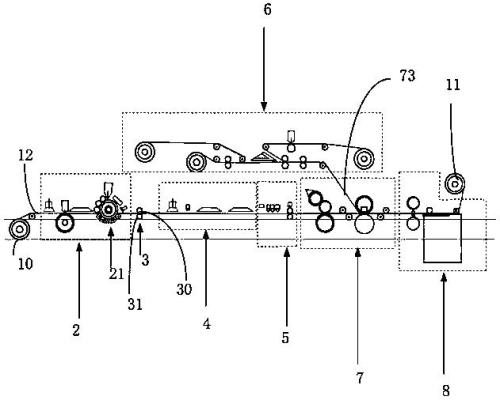
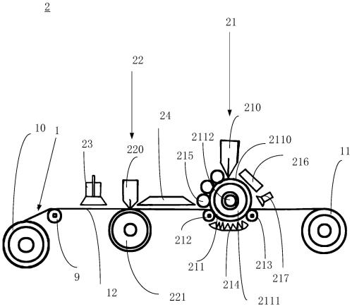
The invention discloses an electrode printing device for a microfluidic chip. The microfluidic chip printing system includes a second conveying component; a cutting component, the cutting component includes a circular film cutter, a cutting roller, The traction roller, the circular film cutter and the cutting roller are arranged correspondingly; through the corresponding cooperation of the circular film cutter and the cutting roller, the electrode sheet and the electrode sheet surrounding are pressed and cut out on the second conveying substrate Yu Ke; the traction roller is far away from the second head end roller. For discharging the remaining material, the present invention uses the printing principle combined with the microfluidic chip manufacturing process to print the microfluidic chip.

Description

technical field [0001] The invention relates to the field of microfluidic technology, in particular to an electrode printing device and a printing method for a microfluidic chip. Background technique [0002] Microfluidic chip is a new interdisciplinary field and an important development frontier in many fields such as analytical science, micro-electromechanical processing, life science, chemical synthesis, analytical instruments and environmental science in the new century. [0003] The processing technology of microfluidic analysis chips originated from the microfabrication of semiconductor and integrated circuit chips, but the processing size of the chip channel is much larger than that of large-scale integrated circuits. The size of the chip is about a few square centimeters, and the width and depth of the microchannel are on the order of microns. On the other hand, the selection of chip materials, the design of microchannels, the surface modification of microchannels an...

Claims


Application Information

Patent Timeline
Patent Type & Authority Patents(China)
IPC IPC(8): B01L3/00B05C1/08B05C5/00B05C5/02B05C13/02B05D3/00
Inventor 林森冯洁云刘俊杰钟伟兴钟华
Owner 深圳博华仕科技有限公司
Learn More