Machining tool for cylindrical workpieces

A cylindrical workpiece and tooling technology, applied in the field of cylindrical workpiece processing tooling, can solve the problems of inability to realize the rotation of the workpiece, inconvenient use, low processing efficiency, etc., and achieve improved versatility and reliability, high automation, and clamping efficiency. high effect

Active Publication Date: 2015-10-21
ANHUI SCI & TECH UNIV
View PDF5 Cites 28 Cited by
  • Summary
  • Abstract
  • Description
  • Claims
  • Application Information

AI Technical Summary

Problems solved by technology

[0002] At present, for the processing of cylindrical workpieces, screw clamps are generally used to directly press the outer surface of the cylinder for processing. When unloading the workpiece, the workpiece must be pulled back or rotated by 90° to remove the workpiece. The auxiliary time is long, sometimes limited by the structure of the fixture or other aspects, the pressure plate has to be raised very high, and then pulled or rotated to take out the parts
In this way, it is very inconvenient to use
The processing efficiency is very low, and the current cylindrical workpiece processing tooling cannot realize the rotation of the workpiece. When the workpiece needs to be rotated, the clamping situation of the workpiece needs to be disassembled again, which is very inconvenient. The need for clamping and the ability to realize the free and convenient rotation of cylindrical workpiece processing tooling for cylindrical workpieces are technical problems that people have always hoped to solve.

Method used


Image

  • Machining tool for cylindrical workpieces

Examples


Embodiment Construction

[0018] The present invention will be described in detail below in conjunction with the accompanying drawings. However, it should be understood that the accompanying drawings are provided only for better understanding of the present invention, and they should not be construed as limiting the present invention.

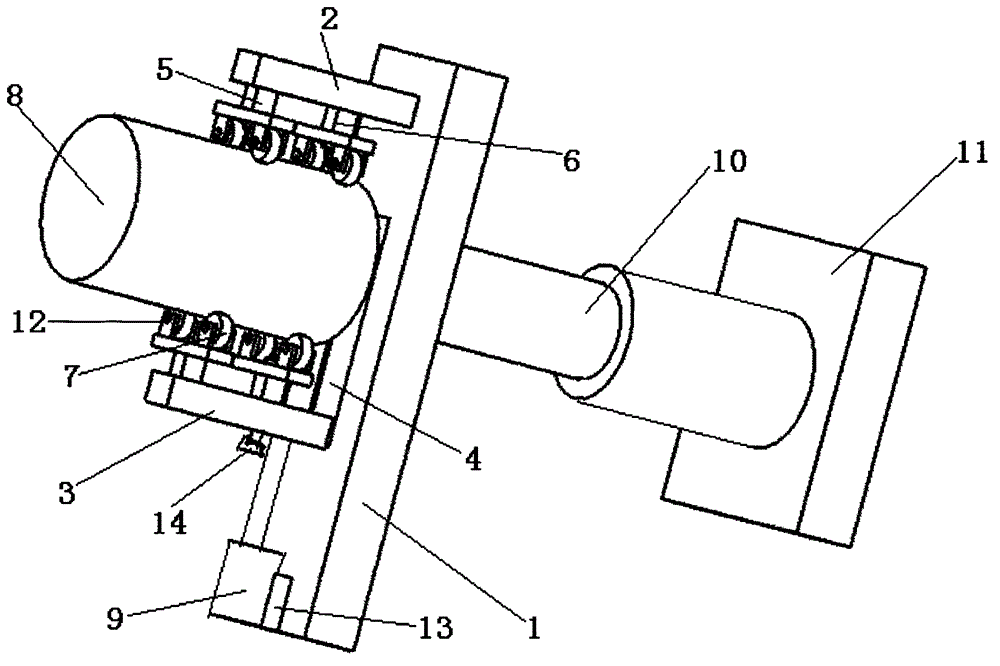
[0019] Such as figure 1 As shown, the present invention provides a cylindrical workpiece processing tool, which includes a base plate 1, a fixed support 2, a movable support 3, a chute-4, a fixed roller frame 5, a sliding roller frame 6, rolling 7 wheels, a cylinder-9, and a cylinder Two 10 and locking bolts 14, one end of the upper surface of the base plate 1 is provided with a fixed bracket 2, and the other end of the upper surface of the base plate 1 is provided with a chute-4, and the chute-4 is provided with a The movable support 3 that chute one 4 slides, and the movable support 3 adopts locking screw (not shown in the figure) to be locked on the chute one 4, and...


PUM


Abstract

The invention provides a machining tool for cylindrical workpieces. The machining tool comprises a bottom plate, a fixed support, a movable support, a first sliding groove, a fixed roller carrier, a sliding roller carrier, rollers, a first air cylinder, a second air cylinder and a locking bolt. By the adoption of the rollers, rapid workpiece clamping and accurate centering can be achieved, and workpieces can rotate conveniently in grinding or turning or welding or the like. By the adoption of the action of the air cylinders, automatic workpiece clamping can be achieved. By the arrangement of the first sliding groove and a second sliding groove, the distance between the fixed support and the movable support and the distance between the sliding roller carrier and the fixed roller carrier can be adjusted according to needs so that workpieces of different diameters can be clamped or different portions of workpieces can be clamped, and accordingly the universality and reliability of the tool are improved. The machining tool for the cylindrical workpieces is high in automation degree and clamping efficiency, greatly shortens the workpiece machining period, improves productivity and lowers the production cost.

Description

technical field [0001] The invention relates to the technical field of mechanical processing, in particular to a cylindrical workpiece processing tool, which belongs to the technical field of workpiece clamping and fixtures. Background technique [0002] At present, for the processing of cylindrical workpieces, screw clamps are generally used to directly press the outer surface of the cylinder for processing. When unloading the workpiece, the workpiece must be pulled back or rotated by 90° to remove the workpiece. The auxiliary time is long, sometimes limited by the structure of the fixture or other aspects, the pressure plate has to be raised very high, and then pulled or rotated to take out the parts. Like this, it is very inconvenient to use. The processing efficiency is very low, and the current cylindrical workpiece processing tooling cannot realize the rotation of the workpiece. When the workpiece needs to be rotated, the clamping situation of the workpiece needs to b...

Claims


Application Information

Patent Timeline
Patent Type & Authority Applications(China)
IPC IPC(8): B23Q3/08B23K37/053B24B41/06
CPCB23K37/0538B23Q3/08B23Q2703/04B24B41/067
Inventor 李忠芳张华马万征张春燕乔印虎
Owner ANHUI SCI & TECH UNIV
Why Eureka
Try Eureka