High-pressure shock absorber and high-pressure descaling system adopting same

A shock absorber and high-pressure technology, which is applied to components of pumping devices for elastic fluids, machines/engines, variable displacement pump components, etc., can solve the problem of short service life of high-pressure energy storage shock absorbers, spare parts costs and Problems such as large manpower input, to achieve the effect of reducing the peak and trough, the curve of water pressure-time is gentle, and the water pressure of descaling is stable

Pending Publication Date: 2019-05-10
MAANSHAN IRON & STEEL CO LTD
View PDF0 Cites 2 Cited by
  • Summary
  • Abstract
  • Description
  • Claims
  • Application Information

AI Technical Summary

Problems solved by technology

The drainage frequency of the three-plunger high-pressure water pump is about 15 (times / second), and the high-pressure water flow has a high-frequency impact on the capsule-type high-pressure energy-storage shock absorber, resulting in a short service life of the high-pressure energy-storage shock absorber, and frequent replacement of oil valves , skins, and shells cannot adapt to the fast pace of production, and the cost of spare parts and manpower investment are large. In order to solve such technical problems, a high-pressure shock absorber with a longer service life and that can be used in high-pressure phosphorus removal systems

Method used


Image

  • High-pressure shock absorber and high-pressure descaling system adopting same
  • High-pressure shock absorber and high-pressure descaling system adopting same
  • High-pressure shock absorber and high-pressure descaling system adopting same

Examples


Embodiment Construction

[0031] The specific implementation manner of the present invention will be described in further detail below by describing the best embodiment with reference to the accompanying drawings.

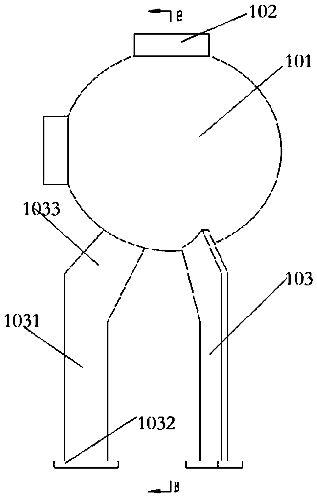
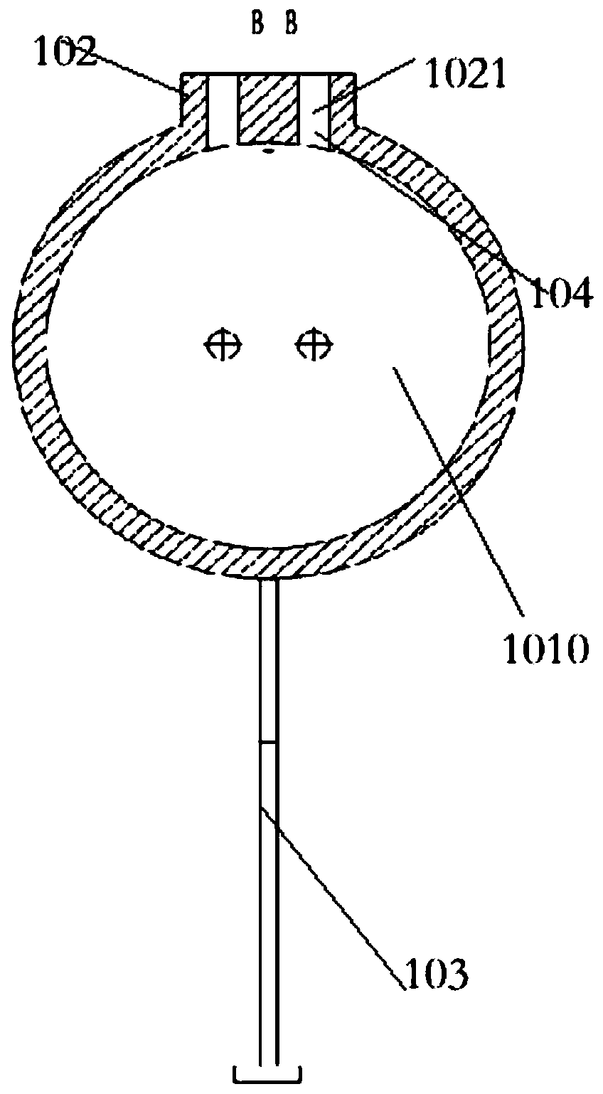
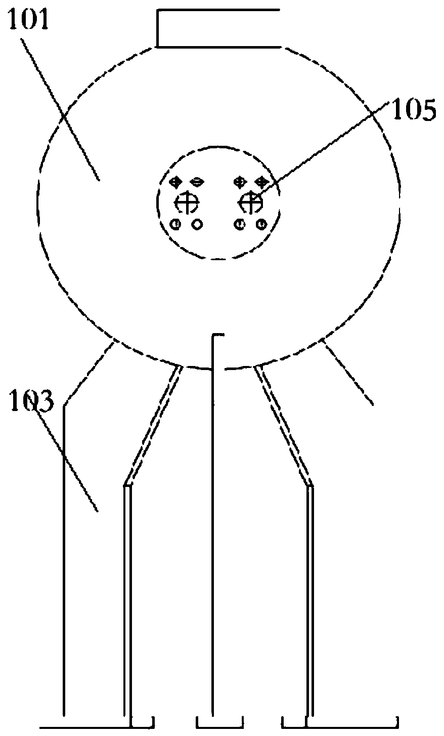
[0032] A high-pressure shock absorber, the high-pressure shock absorber 1 includes a spherical shock absorber 101, the interior of the spherical shock absorber 101 is provided with a storage cavity 1010, and the spherical shock absorber 101 is provided with an inlet for liquid The liquid channel 104 and the liquid discharge channel 105 for liquid discharge, the liquid inlet channel 104 and the liquid discharge channel 105 are intersected and arranged; the liquid inlet channel 104 and the liquid discharge channel 105 are all communicated with the storage cavity 1010; the present invention A new type of high-pressure shock absorber 1 structure is disclosed, which can be well applied to high-pressure phosphorus removal systems. The high-pressure spherical shock absorber 101 disclosed in the pre...


PUM


Abstract

The invention relates to the field of high-pressure shock absorbers, in particular to a high-pressure shock absorber and a high-pressure descaling system adopting the same. The high-pressure shock absorber comprises a spherical shock absorber, a storage cavity is formed in the spherical shock absorber, a liquid inlet channel used for feeding liquid and a liquid discharging channel used for discharging the liquid are arranged on the spherical shock absorber, the liquid inlet channel and the liquid discharge channel are arranged in an intersected mode, and the liquid inlet channel and the liquiddischarge channel are communicated with the storage cavity. According to the high-pressure spherical shock absorber disclosed by the invention, the internal cavity of the spherical shock absorber isoptimized, meanwhile, the distribution positions of the liquid inlet channel and the liquid discharge channel are optimized, so that the liquid inlet channel and the liquid discharge channel are not collinear, water flow impact direction can be changed, high-pressure water flow enters to impact spherical inner walls from the top of the high-pressure spherical shock absorber, the reflected high-pressure water flow and pulsating high-pressure water flow from behind are converged together to weaken the pulsation wave peak of the high-pressure water, and the pulsation condition of the high-pressure water flow passing through the high-pressure shock absorber is improved.

Description

technical field [0001] The invention relates to the field of high-pressure shock absorbers, in particular to a high-pressure shock absorber and a high-pressure phosphorus removal system using the shock absorber. Background technique [0002] The descaling pump station is a common setting in modern industry. Generally, it is equipped with a three-plunger high-pressure water pump produced by Germany WEPUKO. In order to alleviate the impact of high-pressure water pulsation on equipment and pipe networks, a pump is installed on the outlet side of each plunger pump. Only 12L capsule type high-pressure energy storage shock absorber, the system working pressure is 36MPa. The drainage frequency of the three-plunger high-pressure water pump is about 15 (times / second), and the high-pressure water flow has a high-frequency impact on the capsule-type high-pressure energy-storage shock absorber, resulting in a short service life of the high-pressure energy-storage shock absorber, and fre...

Claims


Application Information

Patent Timeline
IPC IPC(8): F04B53/00
Inventor 胡钢裴令明王程雷杰周峰殷文忠
Owner MAANSHAN IRON & STEEL CO LTD
Why Eureka
Try Eureka