Differential pressure type laminar flow measuring method and device

A flow measurement device and flow measurement technology, which are used in the detection of fluid flow by measuring differential pressure, volume/mass flow generated by mechanical effects, etc. Good flow adaptability and easy follow-up correction

Pending Publication Date: 2019-05-10
CHINA JILIANG UNIV +1
View PDF0 Cites 6 Cited by
  • Summary
  • Abstract
  • Description
  • Claims
  • Application Information

AI Technical Summary

Problems solved by technology

However, this method requires two differential pressure sensors, which introduces measurement errors caused by performance differences between differential pressure sensors and increa

Method used


Image

  • Differential pressure type laminar flow measuring method and device
  • Differential pressure type laminar flow measuring method and device
  • Differential pressure type laminar flow measuring method and device

Examples


Embodiment Construction

[0030] The present invention will be further described below by means of the accompanying drawings.

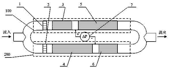
[0031] Such as figure 1 As shown, the measuring pipeline of the pressure head type laminar flow measuring device of the present invention is composed of two parallel branches of branch one 100 and branch two 200 with the same pipe diameter, and two laminar flow elements with different lengths are connected in series on each branch , laminar flow element one 3 and laminar flow element three 5 are installed in series on branch one 100 , laminar flow element two 4 and laminar flow element four 6 are installed in series on branch two 200 . The diameter and number of capillaries inside the laminar flow element are the same, and the lengths of the laminar flow elements on the two branches are the same in pairs, that is, the shorter laminar flow element one 3 and the laminar flow element four 6 are the same, and the longer laminar flow element Element two 4 is the same as laminar fl...


PUM


Abstract

The invention discloses a differential pressure type laminar flow measuring method and device. A measuring pipeline consists of two parallel branch circuits with the same pipe diameter, each branch circuit is in series connection with two laminar flow elements of different lengths, the laminar flow elements on the two branch circuits are identical in pairs,themounting positions of the laminar flowelements are symmetric in a crossedmode, and the two branch circuits which are identical except for the relative positions of a long laminar flow element and a short laminar flow element; and a pressure tappingport is formed in the middle of a pressure tappingcavity between the two laminar flow elements on each branch circuit, the pressure difference between the two pressuretapping cavities is measured and is called as the differential pressure, the differential pressure value isdirectly proportional to the volume flow flowing through the measuring pipeline, the measured volume flow is calculated through the differential pressure by adopting a Hagen-Poiseuille law, and during specific implementation, the requirements that the capillary length of each laminar flow element exceeds the length of a flow inlet section and flowing is in a laminar state are met. According to the differential pressure type laminar flow measuring method, the nonlinear influence of the pressure loss of inlets and outlets and the flow pressure loss of the inlet section of the laminar flow elements of a traditional laminar flowmeter is avoided, and accurate measurement and the wider measuring range are easy to realize.

Description

technical field [0001] The invention relates to the technical field of flow measurement, in particular to a pressure head difference type laminar flow measurement method and device. Background technique [0002] The laminar flow meter has the advantages of no moving parts and the ability to measure instantaneous flow. It is widely used in the field of micro gas flow measurement and instantaneous gas flow measurement. [0003] The laminar flow meter is based on the linear relationship between the flow rate and the pressure loss flowing through the laminar flow element, that is, the Hagen-Besueuye law. However, the linear relationship between flow rate and pressure loss is only true when laminar flow is fully developed. Since the kinetic energy loss at the inlet and outlet of the laminar flow element of the actual laminar flow meter and the flow resistance loss at the inlet section of the capillary are nonlinear, in order to reduce the proportion of nonlinear pressure loss an...

Claims


Application Information

Patent Timeline
IPC IPC(8): G01F1/36
Inventor 张洪军黄浩钦豆峰
Owner CHINA JILIANG UNIV
Why Eureka
Try Eureka