Interference protection elastic fixing jaw

An elastic fixing and fixing claw technology, applied in the field of optical communication, can solve the problems such as the clamping device cannot limit the clamping force, and the components are easily broken and cracked.

Inactive Publication Date: 2019-05-10
GUANGXUN SCI & TECH WUHAN
View PDF6 Cites 0 Cited by
  • Summary
  • Abstract
  • Description
  • Claims
  • Application Information

AI Technical Summary

Problems solved by technology

[0003] The embodiment of the present application solves the problem that the clamping device in the prior art cannot limit the clamping force

Method used


Image

  • Interference protection elastic fixing jaw
  • Interference protection elastic fixing jaw
  • Interference protection elastic fixing jaw

Examples


Embodiment Construction

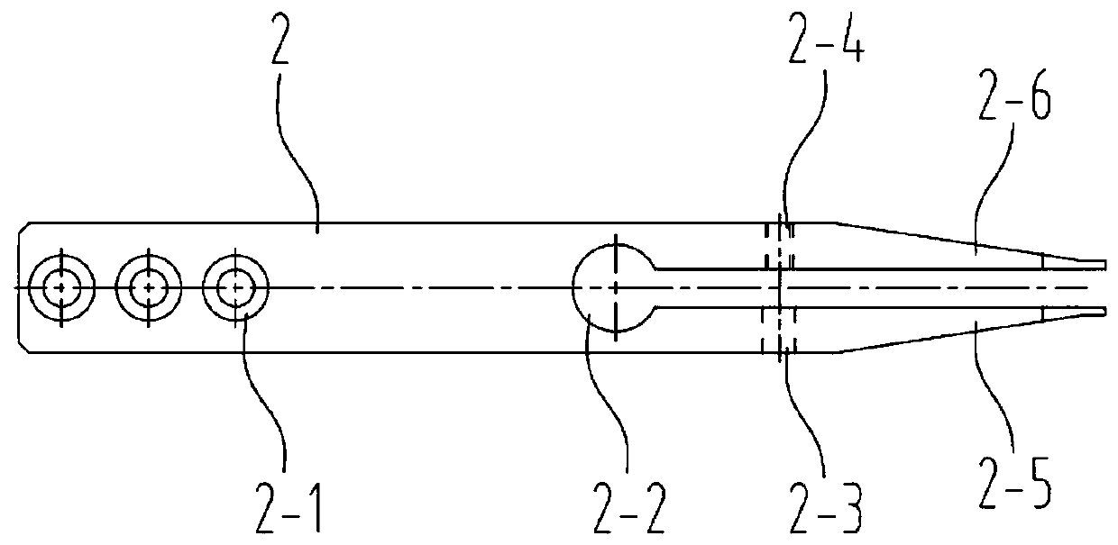
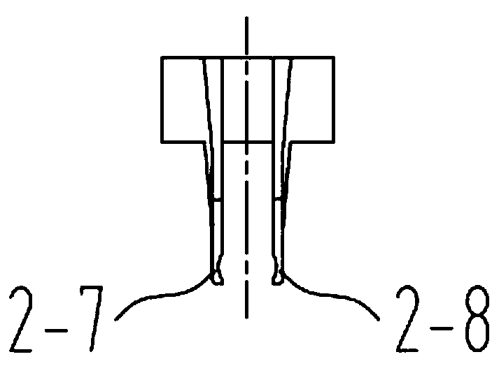
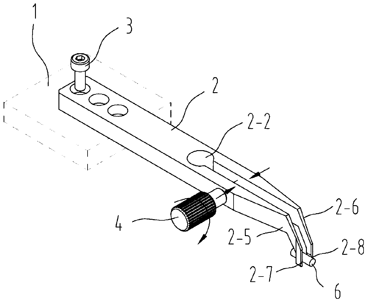
[0035] During the manufacturing process of optical communication products, various components (optics, ceramics, etc., hereinafter referred to as components) need to be clamped and fixed. Commonly used clamping devices in the prior art such as Figure 1-3 As shown, the operation process mainly includes: fixing the fixing claw 2 on the table 1 through the fixing hole 2-1 with the first fixing screw 3, passing the locking screw 4 through the locking hole 2-3, and screwing it clockwise on the lock Tighten screw holes 2-4. The elastic slot 2-2 on the fixed claw is deformed by force, and the left clamp located at the front end of the left clamp arm 2-5 is The mouth 2-7 and the right clamping mouth 2-8 located at the front end of the right clamping arm 2-6 generate mutual displacement and draw inward, and the clamped element 6 is clamped and fixed. If you continue to turn the locking screw 4 clockwise, the force and deformation of the elastic slot 2-2 will continue to increase, wh...


PUM


Abstract

The invention belongs to the technical field of optical communication and discloses an interference protection elastic fixing jaw, comprising a fixing jaw body and clamping arms, wherein the clampingarms are connected with a front end of the fixing jaw body. The clamping arms comprise a first clamping arm and a second clamping arm. A first limiting clamping point and a second limiting clamping point are set on the fixing jaw body. The first limiting clamping point and the second limiting clamping point are used for limiting displacement of the first clamping arm and the second clamping arm. According to the fixing jaw, the problem that in the prior art, an element is easily clamped to break and crack due to the fact that clamping force of a clamping device cannot be limited is solved, theelement can be prevented from being clamped to break and crack, and the clamped element can be protected well.

Description

technical field [0001] The invention relates to the technical field of optical communication, in particular to an elastic fixing claw for interference protection. Background technique [0002] In the manufacturing process of optical communication products, various components inevitably need to be aligned, adjusted and coupled after the components are clamped. Component types of optical communication products, such as: glass lens, glass slide, FA, waveguide, chip, silicon wafer, ceramic PD, backlight PD, optical fiber, collimator, isolator, etc., most of which are fragile. Extra care should be taken when aligning and clamping components during coupling, and attention should be paid to the protection of components. In the manufacturing process of optical communication products, it sometimes happens that the component is under too much force during the clamping process, resulting in the component being broken and damaged. The current clamping method is very dependent on peopl...

Claims


Application Information

Patent Timeline
IPC IPC(8): G02B7/00
Inventor 黄杰丛曹俊红杨宇翔
Owner GUANGXUN SCI & TECH WUHAN
Why Eureka
Try Eureka