New-type base station antenna

A base station antenna, a new type of technology, applied in the field of communication, can solve problems such as time-consuming, labor-intensive, and potential safety hazards, and achieve the effect of simple and convenient operation and improved safety

Active Publication Date: 2019-05-10
深圳国人通信技术服务有限公司
View PDF17 Cites 7 Cited by
  • Summary
  • Abstract
  • Description
  • Claims
  • Application Information

AI Technical Summary

Problems solved by technology

[0004] However, the above-mentioned base station antenna is fixed on the pole by bolts and nuts. When the antenna needs to be repaired or replaced, workers need to climb up the pole to repair or remove the antenna. Such high-altitude operations are time-consuming and labor-intensive, and there is a certain degree of safety. Hidden danger

Method used


Image

  • New-type base station antenna
  • New-type base station antenna
  • New-type base station antenna

Examples


Embodiment 1

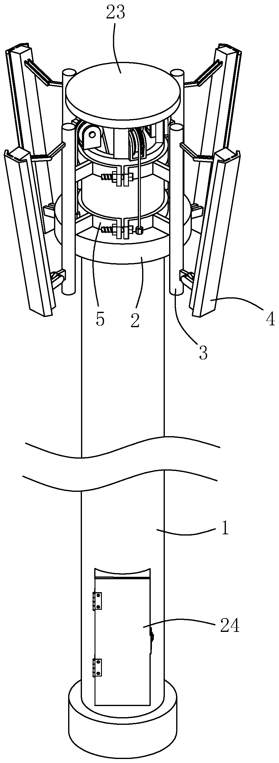
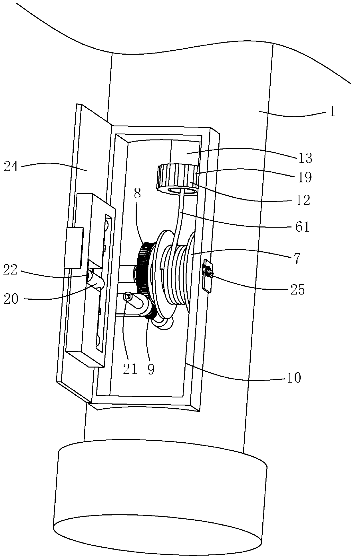
[0033] Embodiment 1: a novel base station antenna 4, such as figure 1 and figure 2 As shown, it includes a hollow pole 1, a movable tube 2 sleeved outside the pole 1, a mounting frame 3 abutting on the movable tube 2, and an antenna 4 fixed on the mounting frame 3. The mounting frame 3 includes two The inner arc plate 5 that is detachably connected to the outer wall of the holding pole 1 is installed inside the holding pole 1 for pulling the movable tube 2 to rise along the holding pole 1. The inner wall of the holding pole 1 is rotatably connected with a rope receiving reel 7. One end of the stay rope is fixedly connected with the movable tube 2, and the other end passes through the top of the holding rod 1 and is fixedly connected with the rope receiving reel 7; The meshing worm 9 is located at the bottom of the holding rod 1 , and the holding rod 1 is provided with an operation port 10 at the worm 9 .

[0034]By coordinating the worm screw 9 with the worm wheel 8, the se...

Embodiment 2

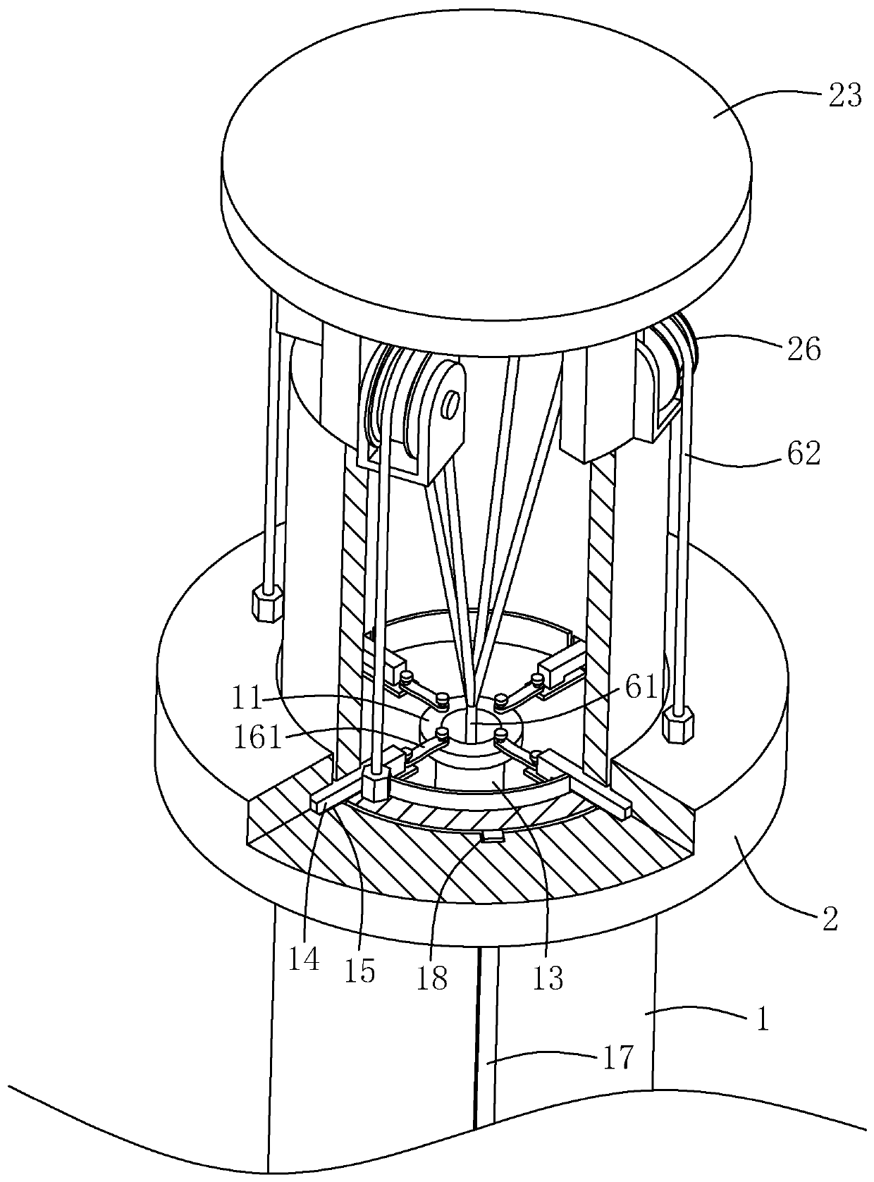
[0041] Embodiment 2: a novel base station antenna 4, such as Figure 4 As shown, the difference between this embodiment and Embodiment 1 is that the transmission assembly includes four wedge-shaped blocks 162 corresponding to the auxiliary block 14 and a spring 163 sleeved on the auxiliary rod; the four wedge-shaped blocks 162 are uniformly integrally formed on the turntable 11, and respectively against the ends of the auxiliary block 14, the two ends of the spring 163 are respectively fixed on the inner wall of the auxiliary block 14 and the pole 1, and under the natural state of the spring 163, the auxiliary block 14 retracts into the pole 1 , the end of the auxiliary block 14 is always pressed against the inclined surface of the wedge block 162 through the spring 163, and the rotation of the turntable 11 makes the end of the auxiliary block 14 press against different positions of the wedge block 162, so that the wedge block 162 drives the auxiliary The block 14 moves horizo...


PUM


Abstract

The invention relates to a new-type base station antenna. The new-type base station antenna comprises a hollow pole, a movable tube sleeved outside the pole, a mounting bracket abutting the movable tube, and an antenna fixed on the mounting bracket; the mounting bracket includes two inner arc plates that are detachably connected and abutted against the outer wall of the pole; a pull cord for pulling the movable tube to rise along the pole is arranged in the pole; the inner wall of the pole is rotatably connected with a cord collecting reel; one end of the pull cord is fixedly connected to themovable tube, and the other end is fixedly connected to the cord collecting reel through the top end of the pole; a worm gear is arranged on a shaft of the cord collecting reel; the inner wall of thepole is rotatably connected with a worm meshing with the worm gear; the worm is at the bottom of the pole; and the pole is provided with an operation port at the location of the worm. By matching theworm and the worm gear, the self-locking of the cord collecting reel can be realized, so that the situation that the cord collecting reel rotates when the worm does not rotate is reduced; and the rotation of the cord collecting reel causes the pull cord to wrap around the cord collecting reel, so as to pull the movable tube up along the pole; therefore, the operation is simple and convenient, andthe security is improved.

Description

technical field [0001] The invention relates to the technical field of communications, in particular to a novel base station antenna. Background technique [0002] In engineering systems such as wireless communication, radio and television, radar, and navigation of aviation and navigation, radio waves are required to transmit information to complete the work of the entire system. Antennas are the basic devices used to transmit and receive radio waves in these systems. [0003] At present, the Chinese patent with the notification number CN205790317U discloses a base station antenna, including an antenna, a pole, a mounting assembly and an angle adjustment piece; the mounting assembly includes a first mounting part and a second mounting part, and the upper end of the antenna passes through the The first mounting part is rotatably connected to the pole, and the lower end of the antenna is rotatably connected to the pole through the second mounting part; the first mounting part ...

Claims


Application Information

Patent Timeline
IPC IPC(8): H01Q1/12H01Q1/24
Inventor 高硕
Owner 深圳国人通信技术服务有限公司
Why Eureka
Try Eureka