
Multi-plane punching die

A punching and die technology, applied in the field of multiple plane punching die, can solve the problems of cumbersome, not well guaranteed hole position accuracy, time-consuming and labor-intensive, etc.

Inactive Publication Date: 2019-05-14
丹阳市景顺塑料制品有限公司
View PDF5 Cites 1 Cited by
  • Summary
  • Abstract
  • Description
  • Claims
  • Application Information

AI Technical Summary

Problems solved by technology

This kind of production operation is cumbersome, time-consuming and labor-intensive, and the hole position accuracy of production and processing cannot be well guaranteed

Method used


Image

  • Multi-plane punching die

Examples


Embodiment Construction

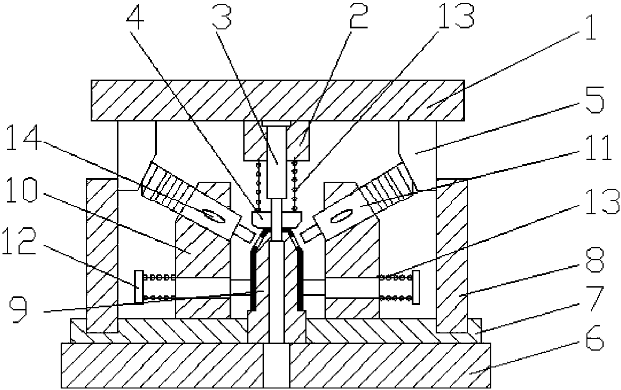
[0012] like figure 1 Shown is a plurality of plane punching dies, mainly composed of an upper mold mechanism and a lower mold mechanism; the lower mold mechanism is arranged below the upper mold mechanism; 3. The unloading plate 4 and the inclined wedge 5 are composed; the fixed sleeve 2 is set under the upper template 1, the punch 3 is connected to the fixed sleeve 2, the unloading plate 4 is slidably connected to the lower end of the punch 3, and the inclined wedge 5 It is arranged on both sides of the lower end surface of the upper template 1; the lower mold mechanism is mainly composed of the lower template 6, the reinforcement plate 7, the stopper 8, the die 9, the fixing seat 10, the inclined hole punch 11 and the positioning pin 12; the reinforcement plate 7 is set On the lower template 6, the stoppers 8 are fixedly connected to both sides of the upper end surface of the reinforcement plate 7, the die 9 is connected to the upper end surface of the reinforcement plate 7,...


PUM


Abstract

The invention relates to part punches, in particular to a multi-plane punching die. The multi-plane punching die comprises an upper die mechanism and a lower die mechanism. The lower die mechanism isarranged below the upper die mechanism; the upper die mechanism is mainly composed of an upper die plate, a fixing sleeve, a convex die, an unloading plate and bevel wedges, wherein the convex die isconnected to the fixing sleeve; the unloading plate is slidably connected to the lower end of the convex die; and the bevel wedges are arranged on both sides of the lower end of the upper die plate. The lower die mechanism is mainly composed of a lower die plate, a reinforcing plate, stop blocks, a concave die, fixing seats, bevel hole convex dies and positioning pins, wherein the reinforcing plate is arranged on the lower die plate; the stop blocks are fixedly connected to both sides of the upper end face of the reinforcing plate; the concave die is connected to the upper end face of the reinforcing plate; the fixing seats are arranged on both sides of the concave die; the bevel hole convex dies are arranged on the upper portions of the fixing seats; and the positioning pins are arrangedon the lower portions of the fixing seats. With adoption of the structure, multiple different planes can be punched at the same time; the punching precision is ensured; the punching procedure is simplified; the production efficiency is improved; and the production cost is reduced.

Description

technical field [0001] The invention relates to the equipment field of stamping parts, in particular to a plurality of plane punching dies. technical background [0002] Stamping parts are formed by applying external force to plates, strips, pipes and profiles by presses and molds to cause plastic deformation or separation, thereby obtaining workpieces of required shape and size. In the production process of stamping parts, the stamping die is one of the most important pieces of equipment. The types of stamping dies include punching dies, blanking dies, flanging dies, folding dies, and hole expansion dies. Among them, punching dies It is one of the most commonly used sets of equipment in stamping dies. Traditional punching dies are used to punch holes in the same plane. When punching holes on different planes, another process needs to be set up, and positioning is required to ensure that the holes in the second process are on the plane. s position. Such production operati...

Claims


Application Information

Patent Timeline
Patent Type & Authority Applications(China)
IPC IPC(8): B21D28/34
Inventor 景海俊
Owner 丹阳市景顺塑料制品有限公司
Learn More