Automatic abrasive paper punching and cutting machine

An automatic punching machine and sandpaper technology, applied in metal processing and other directions, can solve the problems of increasing friction, increasing noise, and low service life, and achieve the effects of ensuring punching accuracy, improving machining accuracy and long service life.

Pending Publication Date: 2019-01-04
YANCHENG HUASEN MACHINERY
View PDF11 Cites 1 Cited by
  • Summary
  • Abstract
  • Description
  • Claims
  • Application Information

AI Technical Summary

Problems solved by technology

Existing paper blanking devices usually include a base plate, a fixed template assembly, a movable template assembly and a driving part. Since the movable template assembly moves horizontally along the axial direction of the guide post, and the movable template assembly is affected by its own gravity, the The component force in the direction of gravity of the guide post is relatively large. At this time, the guide post will be deformed during the action of the movable template assembly, which will increase the friction force and increase the noise during work. Since the movable template assembly is usually heavy, the friction force is large. , the movement of the moving mold cannot be precisely controlled. In the actual work process, the processing speed of the moving template assembly is usually reduced to ensure the processing accuracy of the product and avoid paper waste. However, this reduces the production efficiency of the product and increases the production cost.
Moreover, in the specific installation structure, the movement of the moving mold assembly can only be driven by the cylinder, and the direction of travel of the cylinder piston rod is consistent with the moving direction of the moving mold assembly. The volume of the cutting device, so that the volume becomes larger, because the driving force of the cylinder is not large enough, the stroke is long, and the moving die assembly mentioned above makes the guide rail deformed, etc., in the processing process, especially the punching process of paper In the process, the speed can only be reduced to realize the punching of the paper, the processing efficiency is low, and the service life is low

Method used


Image

  • Automatic abrasive paper punching and cutting machine
  • Automatic abrasive paper punching and cutting machine
  • Automatic abrasive paper punching and cutting machine

Examples


Embodiment Construction

[0017] The following will clearly and completely describe the technical solutions in the embodiments of the present invention with reference to the accompanying drawings in the embodiments of the present invention. Obviously, the described embodiments are only some, not all, embodiments of the present invention. Based on the embodiments of the present invention, all other embodiments obtained by persons of ordinary skill in the art without making creative efforts belong to the protection scope of the present invention.

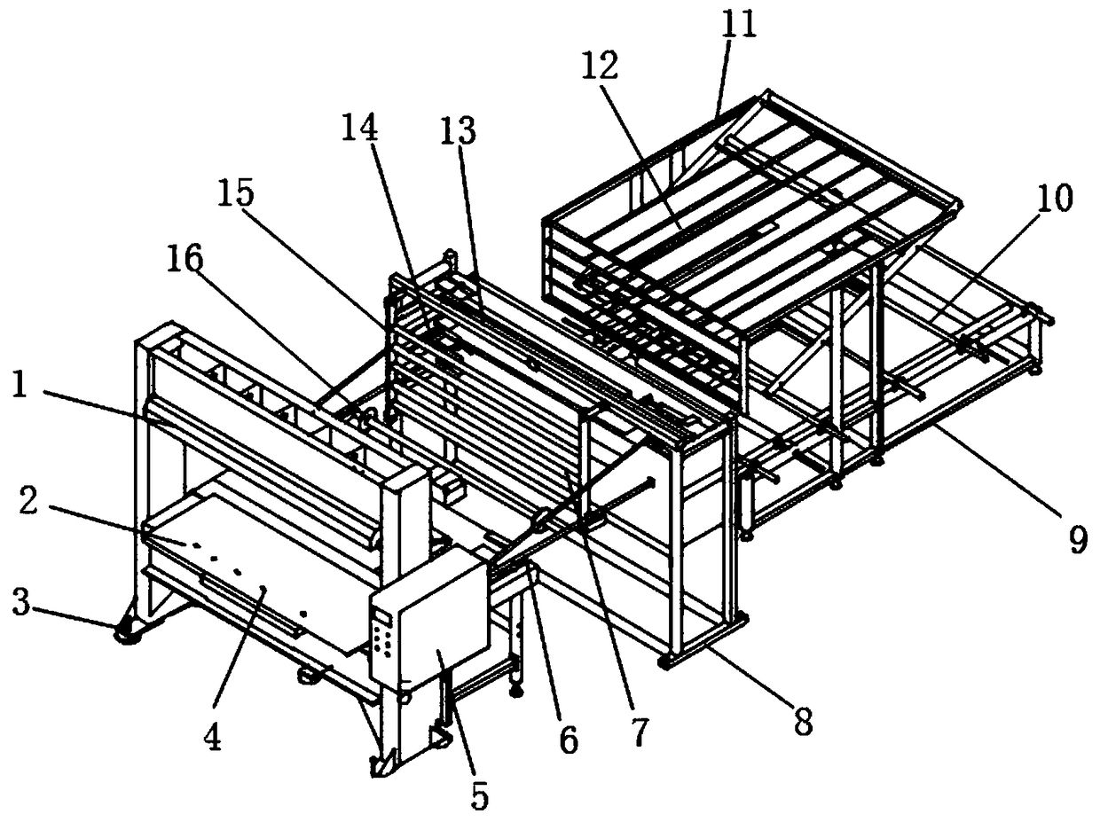
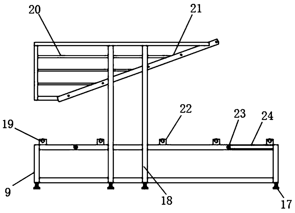
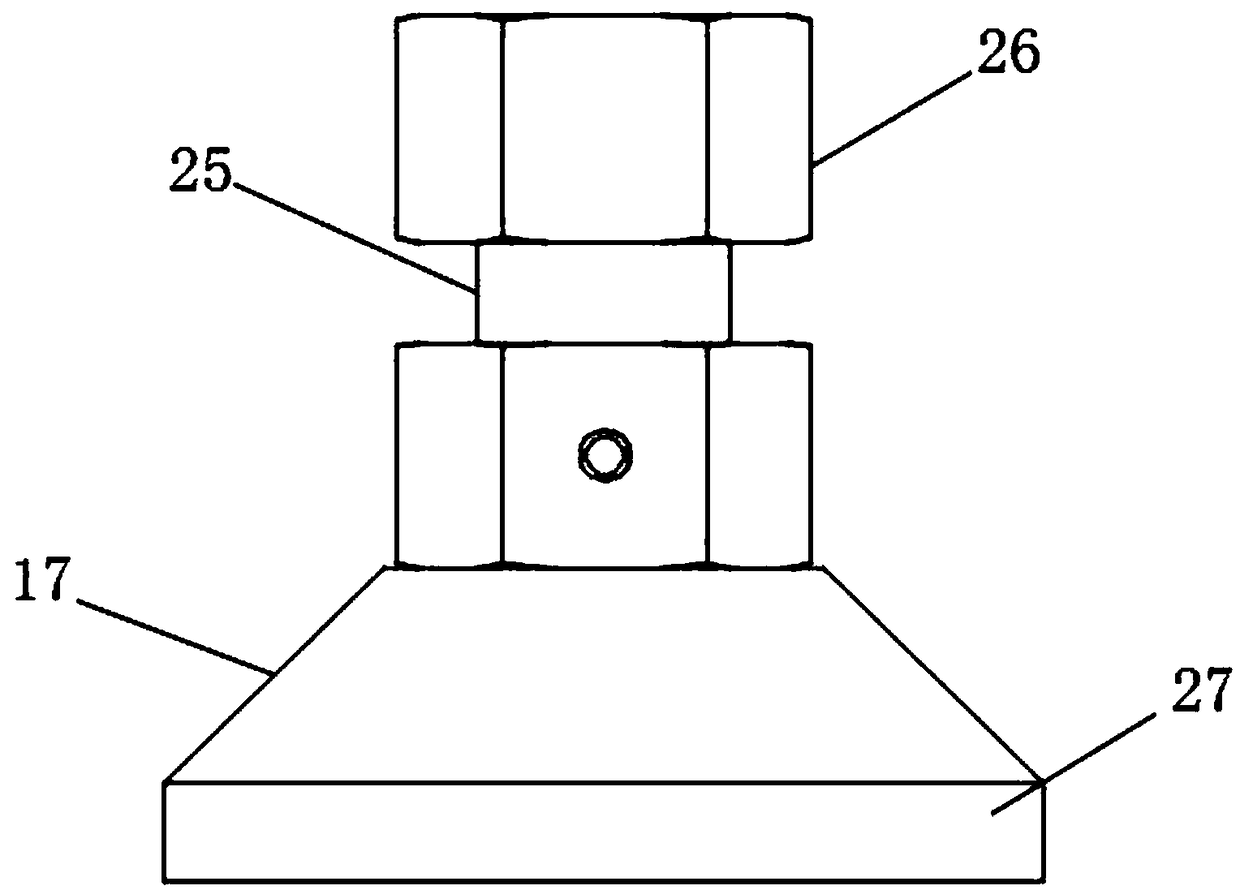
[0018] see Figure 1-3 , the present invention provides a technical solution: an automatic punching machine for sandpaper, including a punching host 1, a paper receiving table 2, a base 3, a mounting hole 4, a driving part 5, a slide bar feeding frame 6, a rolling shaft 7, Fixed frame 8, material receiving channel 9, material receiving rod 10, square groove 11, roll unwinding rack 12, correction shaft 13, correction frame 14, reinforcement rib 15, transmission...


PUM


Abstract

The invention discloses an automatic abrasive paper punching and cutting machine which comprises a punching and cutting main machine, a paper receiving table, a base, a mounting hole, a driving component, a sliding strip feeding frame, a rolling shaft, a fixing frame, a receiving channel, a receiving rod, a square groove, a rolling and unrolling rack, a deviation-rectifying shaft, a deviation-rectifying frame, a strengthening rib, a transmission roller, a footstand, a supporting column, a limiting block, a sliding groove, an inclined plate, a supporting shaft, a conveying roller, a conveying belt, a stud, a nut and a non-slip washer. One side of the driving component is provided with the sliding strip feeding frame, one side of the transmission roller is provided with the deviation-rectifying frame, one side of the deviation-rectifying frame is provided with the rolling and unrolling rack, the outside of the rolling and unrolling rack is provided with the square groove, and the receiving rod is arranged below the rolling and unrolling rack. The invention has the advantages of the simple structure, convenient assembling, reliable action, long service life and the like; and the deviation-rectifying frame is arranged and arranged in front of the rolling and unrolling rack, so that deviation rectifying is carried out on products in front of the punching and cutting device, the punching accuracy of the products, and the processing precision of the products is improved.

Description

technical field [0001] The invention relates to the technical field of punching machines, in particular to an automatic sandpaper punching machine. Background technique [0002] A paper cutter is a commonly used paper processing equipment. The paper automatic punching device is the core working mechanism in the paper cutter. The paper is cut into a specific shape by the punching device. Existing paper blanking devices usually include a base plate, a fixed template assembly, a movable template assembly and a driving part. Since the movable template assembly moves horizontally along the axial direction of the guide post, and the movable template assembly is affected by its own gravity, the The component force in the direction of gravity of the guide post is relatively large. At this time, the guide post will be deformed during the action of the movable template assembly, which will increase the friction force and increase the noise during work. Since the movable template assem...

Claims


Application Information

Patent Timeline
Patent Type & Authority Applications(China)
IPC IPC(8): B26D7/08
CPCB26D7/08B26D2007/082
Inventor 韦杰韦金权陈加林
Owner YANCHENG HUASEN MACHINERY
Why Eureka
Try Eureka