
High-strength production equipment for pulling plate of transformer

A kind of production equipment and high-strength technology, applied in the field of transformer processing, can solve the problems of drilling position deviation, pulling plate displacement, temperature rise, etc., and achieve the effect of ensuring the drilling accuracy

Inactive Publication Date: 2021-03-12
WUXI PUTIAN IRON CORE CO LTD
View PDF8 Cites 1 Cited by
  • Summary
  • Abstract
  • Description
  • Claims
  • Application Information

AI Technical Summary

Problems solved by technology

[0004] The problem to be solved by the present invention is to provide a high-strength counter-drawing production equipment for transformers, which solves the problem that when the existing drawing production equipment drills the drawing, the drill bit moves down and directly contacts the drawing. The hole method is easy to cause the displacement of the drawing plate at the moment of contact between the drill bit and the drawing plate, resulting in a deviation in the drilling position; at the same time, during the drilling process, the temperature rises between the high-speed rotating drill bit and the drawing plate, which affects the drilling. normal technical issues

Method used


Image

  • High-strength production equipment for pulling plate of transformer
  • High-strength production equipment for pulling plate of transformer
  • High-strength production equipment for pulling plate of transformer

Examples


Embodiment approach

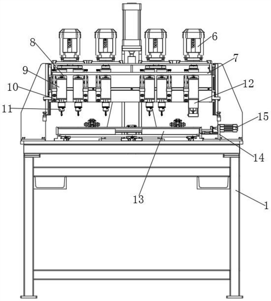
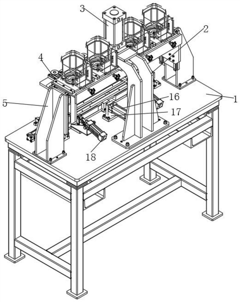
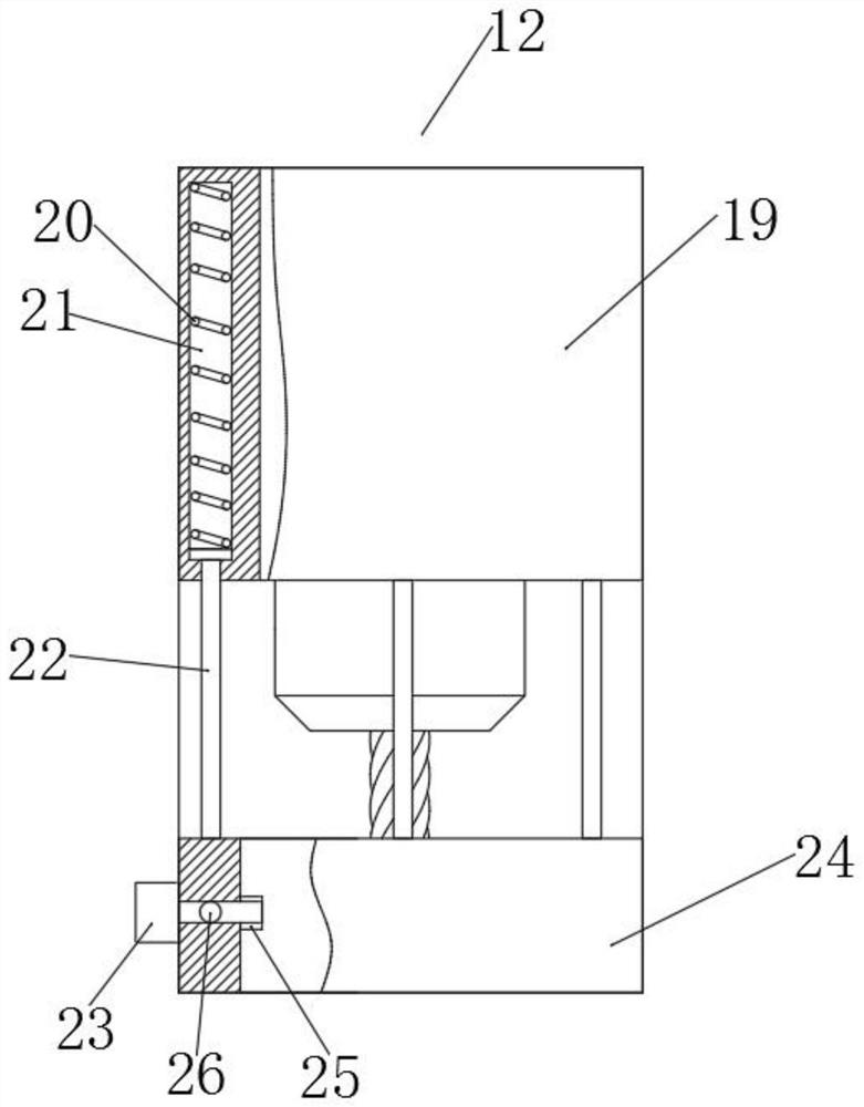
[0033] As an embodiment of the present invention, several installation grooves 21 are vertically opened inside the sleeve 19, and a spring 20 is installed inside the installation groove 21, and the spring 20 is connected with the top end of the movable rod 22, and the bottom end of the movable rod 22 is connected with the lifting The cylinder 24 is connected, and the elevating cylinder 24 first contacts with the top side of the pull plate, and at the same time continues to descend, and the movable rod 22 moves up in the installation groove 21 of the sleeve 19, compresses the spring 20, and plays a buffering role.

[0034] As an embodiment of the present invention, the external joint 23 is connected to the external water pump through a conduit, and the water pump is connected to the water tank, and the water pump transports the water in the water tank to the external joint 23 through the conduit, and then to the nozzle 25 through the internal channel 26 squirt.

[0035] As an e...


PUM


Abstract

The invention discloses high-strength production equipment for a pulling plate of a transformer. The high-strength production equipment for the pulling plate of the transformer comprises a rack and asupporting arm, the supporting arm is installed on the top side of the rack, a first hydraulic rod is installed at the top of the supporting arm, the telescopic end, penetrating through the top of thesupporting arm, of the first hydraulic rod is provided with a lifting table, and a plurality of supporting plates are vertically installed on one side of the lifting table. The first hydraulic rod onthe supporting arm extends to drive the lifting table to descend along a side frame, meanwhile, a servo motor works, a main belt wheel rotates, a rotating shaft is driven to rotate on a shaft seat through transmission of a belt and a driven belt wheel, and then high-speed rotation of a drill bit is achieved; and continuous descending is carried out until a lifting cylinder is firstly in contact with the top side of the pulling plate, continuous descending is carried out at the same time, a movable rod moves upwards in a mounting groove of a sleeve, compressing is carried out on a spring, thereactive force of the spring carries out limitation on the pulling plate through the lifting cylinder while the spring plays a role in buffering, and therefore it is guaranteed that during punching, the phenomenon of displacement of the pulling plate does not occur, and the punching precision is guaranteed.

Description

technical field [0001] The invention relates to the technical field of transformer processing, in particular to a production equipment for high-strength counter-drawing plates of transformers. Background technique [0002] The drawing plate is an auxiliary structure of the transformer, and the drawing plate needs to be drilled during the processing process, and the production equipment in this application is drilling equipment. [0003] When the existing drawing plate production equipment is drilling the drawing plate, the drill bit moves down and directly contacts the drawing plate to drill. There is a deviation in the position; at the same time, during the drilling process, the temperature rises between the high-speed rotating drill bit and the drawing plate, which affects the normal drilling. Contents of the invention [0004] The problem to be solved by the present invention is to provide a high-strength counter-drawing production equipment for transformers, which sol...

Claims


Application Information

Patent Timeline
IPC IPC(8): B23B39/16B23B47/00B23B47/06B23Q11/10
CPCB23B39/161B23B47/00B23Q5/10B23Q11/10
Inventor 蔡子祥王向阳魏龙刘赛罗荣新
Owner WUXI PUTIAN IRON CORE CO LTD
Learn More