Eureka AIR delivers breakthrough ideas for toughest innovation challenges, trusted by R&D personnel around the world.

Construction method for atmospheric pressure shale gas volume fracturing

A technology of gas volume and construction method, which is applied in the field of geological exploration, can solve the problems that the post-pressing production cannot reach the economic exploitation value, and the post-pressing effect is not ideal, so as to improve the level of development technology and economic benefits, and is conducive to comprehensive promotion. , Improve the effect of the transformation volume

Pending Publication Date: 2019-05-14
CHINA PETROLEUM & CHEM CORP +1
View PDF7 Cites 4 Cited by
  • Summary
  • Abstract
  • Description
  • Claims
  • Application Information

AI Technical Summary

Problems solved by technology

[0003] However, limited by the current technical conditions, in many practical application scenarios, although the fracturing construction has been successful, the post-fracturing effect has not been ideal, and the post-fracturing production is far below the economic mining value.

Method used


Image

  • Construction method for atmospheric pressure shale gas volume fracturing
  • Construction method for atmospheric pressure shale gas volume fracturing

Examples


Embodiment 1

[0085] Embodiment 1: Taking well X of a certain shale gas block as an example, the present invention is further described in detail:

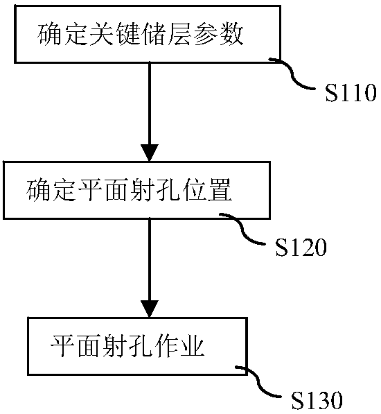
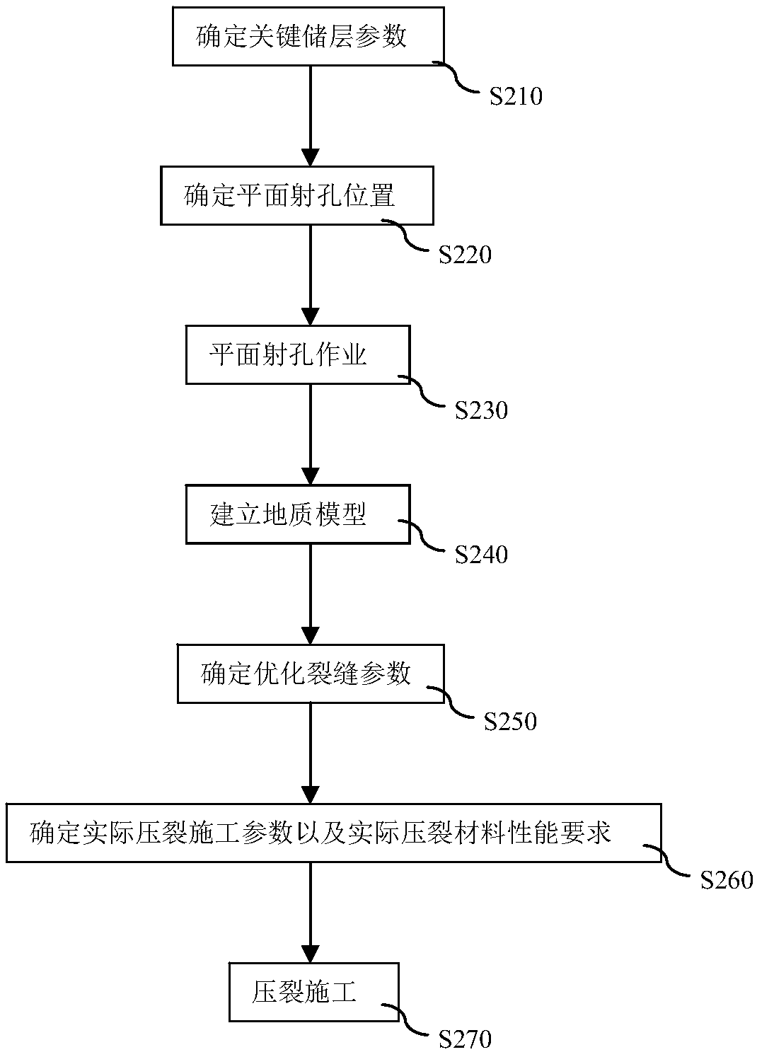
[0086] (1) Fine evaluation of key reservoir parameters

[0087] According to seismic, mud logging, logging, core analysis and other parameters, the evaluation of reservoir lithology, physical properties, gas-bearing properties, rock mechanics, three-dimensional stress, bedding / texture and natural fracture development is carried out.

[0088] (2) Determination of the plane perforation position

[0089] On the basis of (1), combined with geological sweet spot and engineering sweet spot position, determine the position of each plane perforation.

[0090] (3) Perforation operation

[0091] The well adopts hydraulic compression packer + coiled tubing hydraulic jet perforating device + conventional tubing with directional perforating device for plane perforating operation.

[0092] (4) Optimization of fracture parameter system and fracturing const...

Embodiment 2

[0101] Embodiment 2: Taking the Y well in a certain shale gas block as an example, the present invention is further described in detail:

[0102] (1) Fine evaluation of key reservoir parameters

[0103] According to seismic, mud logging, logging, core analysis and other parameters, the evaluation of reservoir lithology, physical properties, gas-bearing properties, rock mechanics, three-dimensional stress, bedding / texture and natural fracture development is carried out.

[0104] (2) Determination of the plane perforation position

[0105] On the basis of (1), combined with geological sweet spot and engineering sweet spot position, determine the position of each plane perforation.

[0106] (3) Perforation operation

[0107] The well adopts hydraulic compression packer + coiled tubing hydraulic jet perforating device + conventional tubing with directional perforating device for plane perforating operation.

[0108] (4) Optimization of fracture parameter system and fracturing con...


PUM


Abstract

The invention discloses a construction method for atmospheric pressure shale gas volume fracturing, comprising the following steps: conducting directional perforating to form two rows of holes in theupper wing and the lower wing of a horizontal well shaft along the direction of the horizontal well shaft on the basis of plane perforation, and forming an orthogonal state with the plane perforation.According to the method disclosed by the invention, the reservoir transformation volume can be greatly increased, so that the problems that the post-fracturing effect cannot reach the expectation andthe stable yield cannot reach the economic exploitation value in the normal-pressure shale gas fracturing technology are solved. By the adoption of the method, the production potential of the reservoir is fully excavated, comprehensive popularization of the volume fracturing technology is facilitated, and great significance is achieved for improving the development technology level and economic benefits of an unconventional oil and gas reservoir.

Description

technical field [0001] The invention relates to the field of geological exploration, in particular to a construction method for volume fracturing of normal-pressure shale gas. Background technique [0002] After the production of oil wells reaches a certain stage, the production capacity and permeability decrease. In order to enhance the oil drainage capacity and increase the production of oil wells, people invented fracturing technology. There are two types of fracturing methods: hydraulic fracturing and high-energy gas fracturing. Hydraulic fracturing is to inject fluid into the well at high speed by the ground high-pressure pump truck unit, and use the high pressure at the bottom of the well to break the rock in the oil layer and produce cracks. In order to prevent the pressure from dropping after the pump truck stops working, the cracks will close up by themselves. The injected liquid after the formation rupture is mixed with sand which is several times denser than the f...

Claims


Application Information

Patent Timeline
IPC IPC(8): E21B43/114E21B43/117E21B43/119E21B43/26E21B43/267
Inventor 蒋廷学刘红磊周林波吴峙颖刘建坤王世栋侯磊
Owner CHINA PETROLEUM & CHEM CORP
Why Eureka
Eureka Blog
Learn More