Flow control valve

A technology of flow control valve and valve body, which is applied in the direction of valve details, valve devices, and devices for absorbing fluid energy of the valve, which can solve problems such as adverse consequences, turbulent flow, and unstable fluid flow rate

Pending Publication Date: 2019-05-14
KAIRUITE VALVE
View PDF9 Cites 1 Cited by
  • Summary
  • Abstract
  • Description
  • Claims
  • Application Information

AI Technical Summary

Problems solved by technology

[0002] The flow control valve is a very important control part on the pipeline conveying fluid medium. The structure of the flow control valve is composed of a valve body, a valve cover, a valve stem, a valve core, a sealing ring and a driving device. The driving device is commonly used The handwheel,

Method used


Image

  • Flow control valve
  • Flow control valve
  • Flow control valve

Examples


Embodiment Construction

[0016] The present invention is specifically described below by way of examples.

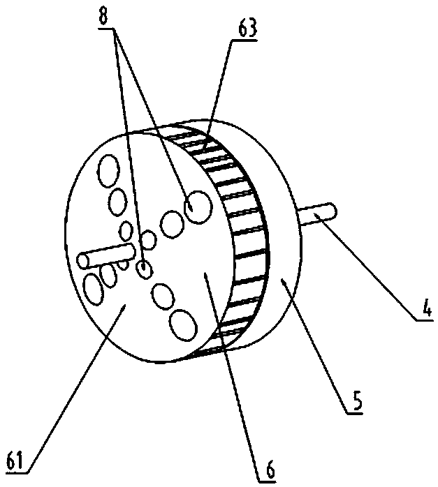
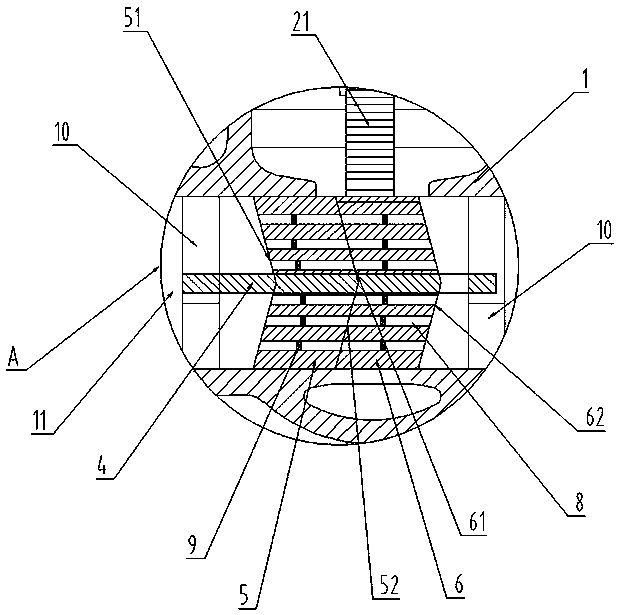
[0017] Such as figure 1 As shown, this embodiment discloses a flow control valve, which includes a valve body 1, a valve cover 2 and a valve stem 3. A flow passage 11 is provided in the valve body 1, and a rotating shaft 4 is provided on the central axis of the flow passage 11. A first deflector plate 5 and a second deflector plate 6 are sheathed on the rotating shaft 4, the first deflector plate 5 is fixed in the flow channel 11, one end of the first deflector plate 5 has a tapered groove 51, and the other One end is a raised conical surface 52, the second baffle 6 also has a conical groove 61 and a raised conical surface 62, the conical groove of the first baffle 5 and the second baffle 6 The conical surface of the second deflector plate 6 abuts against the conical groove of the first deflector plate 5, the second deflector plate 6 is rotatably mounted on the rotating shaft 4, and the first d...


PUM


Abstract

The invention discloses a flow control valve, which comprises a valve body, a valve cover and a valve rod. A flow channel is formed in the valve body, a rotating shaft is arranged at the central axisposition of the flow channel, a first flow-guiding disc and a second flow-guiding disc are arranged on the rotating shaft, the first flow-guiding disc is fixed into the flow channel, conical grooves are formed in one end of the first flow-guiding disc and one end of the second flow-guiding disc correspondingly, protruding conical surfaces are arranged at the other ends of the first flow-guiding disc and the second flow-guiding disc, the conical groove of the first flow-guiding disc is matched with the conical surface of the second flow-guiding disc, the conical surface of the second flow-guiding disc abuts against the interior of the conical groove of the first flow-guiding disc, the second flow-guiding disc is rotationally mounted on the rotating shaft, mutually-corresponding flow-guidingholes are formed in the first flow-guiding disc and the second flow-guiding disc correspondingly, pressure-relieving impeller assemblies are arranged in the flow-guiding holes, and the valve rod andthe second flow-guiding disc are in transmission connection. In this way, a fluid can be stably output after passing, and turbulence in the fluid is avoided.

Description

technical field [0001] The invention relates to a valve, in particular to a flow control valve. Background technique [0002] The flow control valve is a very important control component on the pipeline conveying fluid medium. The structure of the flow control valve is composed of a valve body, a valve cover, a valve stem, a valve core, a sealing ring and a driving device. The driving device is commonly used The handwheel, the driving device drives the valve stem to open and close the valve core to control the flow of the fluid, but after the valve core is opened, the flow rate of the fluid will produce extremely unstable turbulent flow, which will occur when such fluid is used in some special equipment bad consequences. Contents of the invention [0003] In order to solve the above problems, the object of the present invention is to provide a flow control valve for stably delivering fluid. [0004] In order to achieve the above object, the present invention provides the...

Claims


Application Information

Patent Timeline
IPC IPC(8): F16K5/02F16K5/08F16K27/06F16K31/53F16K47/02
Inventor 张清明李运龙彭宇林
Owner KAIRUITE VALVE
Why Eureka
Try Eureka