Hydraulic-control micro-valve gas supply reversing device based on magnetic drive and use method thereof

A technology of reversing device and micro-valve, which is applied in valve device, valve operation/release device, valve details, etc., can solve the problems of low control accuracy, reduced flow efficiency, high cost, and achieves simple device process, resource saving, Easy-to-use effects

Inactive Publication Date: 2017-08-15
KUNMING UNIV OF SCI & TECH
View PDF6 Cites 6 Cited by
  • Summary
  • Abstract
  • Description
  • Claims
  • Application Information

AI Technical Summary

Problems solved by technology

[0002] The multi-way reversing valve is one of the key components in the construction machinery system. With the wide application of micro valves in various fields, the requirements for the reversing valve are getting higher and higher. At present, the main driving methods are mainly pressure-driven reversing and The photosensitive droplet drives the reversing. The main operation is to control the switch of the microvalve by controlling the pressure and the intensity of the light. Its control precision is low, the dynamic response is poor, the cost is high, and the number of times of use will cause

Method used


Image

  • Hydraulic-control micro-valve gas supply reversing device based on magnetic drive and use method thereof

Examples


Embodiment 1

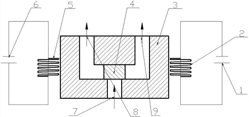
[0033] Embodiment 1: as figure 1 As shown, a gas supply reversing device based on a magnetically driven liquid-controlled microvalve includes a power supply I1, an electromagnetic coil I2, a valve body 3, a magnetic droplet 4, an electromagnetic coil II5, and a power supply II6;

[0034] The bottom of the valve body 3 has an air inlet 7, and the top of the valve body 9 has an air outlet I8 and an air outlet II9 symmetrically. The air inlet 7 communicates with the air outlet I8 and the air outlet II9 through a microchannel, and the magnetic droplet 4 is located at In the microchannel and the width of the magnetic droplet 4 is greater than the width of the air inlet 7, the air outlet I8, and the air outlet II9, the depth and width of the magnetic droplet 4 are respectively equal to the depth and width of the microchannel, and the magnetic droplet 4 can be in the microchannel. Move in the channel, and then block the air outlet I8 or the air outlet II9, the magnetic droplet 4 bloc...


PUM


Abstract

The invention relates to a hydraulic-control micro-valve gas supply reversing device based on magnetic drive and a use method of the hydraulic-control micro-valve gas supply reversing device based on magnetic drive and belongs to the technical field of precise measuring devices. According to the hydraulic-control micro-valve gas supply reversing device based on magnetic drive, the bottom of a valve body is provided with a gas inlet, the top of the valve body is symmetrically provided with a gas outlet I and a gas outlet II, the gas inlet communicates with the gas outlet I and the gas outlet II through a micro-channel, a magnetic liquid drop is located in the micro-channel, the width of the magnetic liquid drop is larger than that of the gas inlet, the gas outlet I and the gas outlet II, the depth and the width of the magnetic liquid drop are equal to the depth and the width of the micro-channel correspondingly, the magnetic liquid drop can move in the micro-channel, so that the gas outlet I or the gas outlet II is blocked, when the magnetic liquid drop blocks the gas outlet I or the gas outlet II, the magnetic liquid drop does not block the gas inlet, and an electromagnetic coil I and the electromagnetic coil II are arranged on the two sides of the valve body correspondingly. By the adoption of the hydraulic-control micro-valve gas supply reversing device based on magnetic drive and the use method of the hydraulic-control micro-valve gas supply reversing device based on magnetic drive, the electromagnetic coils are controlled to generate a magnetic field so that the magnetic liquid drop can be controlled to move, and therefore the micro-valve reversing function is achieved; non-contact type drive can be achieved, the reliability is high, and implementation is easy.

Description

technical field [0001] The invention relates to a gas supply reversing device based on a magnetically driven liquid-controlled microvalve and a method for using the same, belonging to the field of detection of precision equipment performance. Background technique [0002] The multi-way reversing valve is one of the key components in the construction machinery system. With the wide application of micro valves in various fields, the requirements for the reversing valve are getting higher and higher. At present, the main driving methods are mainly pressure-driven reversing and The photosensitive droplet drives the reversing. The main operation is to control the switch of the microvalve by controlling the pressure and the intensity of the light. Its control precision is low, the dynamic response is poor, the cost is high, and the number of times of use will cause certain damage to the valve body. thereby reducing flow efficiency. Disadvantages of photosensitive reversing valve:...

Claims


Application Information

Patent Timeline
IPC IPC(8): F16K31/06F16K11/24
CPCF16K31/0603F16K11/24F16K31/0675
Inventor 龙威柴辉杨绍华裴浩陈娅君吴张永张晓龙魏镜弢王庭有莫子勇
Owner KUNMING UNIV OF SCI & TECH
Why Eureka
Try Eureka