Electric small door actuator assembly on vehicle refueling tank cover or charging tank cover

A charging box and fuel tank technology, applied in the field of auto parts, can solve problems such as the high risk of water entering the actuator, the inability to open the lid of the fuel tank or the charging box, and the exposure of the actuator.

Pending Publication Date: 2021-06-11
NINGBO HUAKAI ELECTRONICS TECH CO LTD
View PDF1 Cites 6 Cited by
  • Summary
  • Abstract
  • Description
  • Claims
  • Application Information

AI Technical Summary

Problems solved by technology

[0005]Actuators similar to the above structure belong to the mainstream actuators on the fuel tank cover or charging box cover of vehicles on the market, after market feedback and continuous use According to the test, it has at least the following defects: 1. It has a strong self-locking force. Once the actuator or

Method used


Image

  • Electric small door actuator assembly on vehicle refueling tank cover or charging tank cover
  • Electric small door actuator assembly on vehicle refueling tank cover or charging tank cover
  • Electric small door actuator assembly on vehicle refueling tank cover or charging tank cover

Examples


Embodiment 1

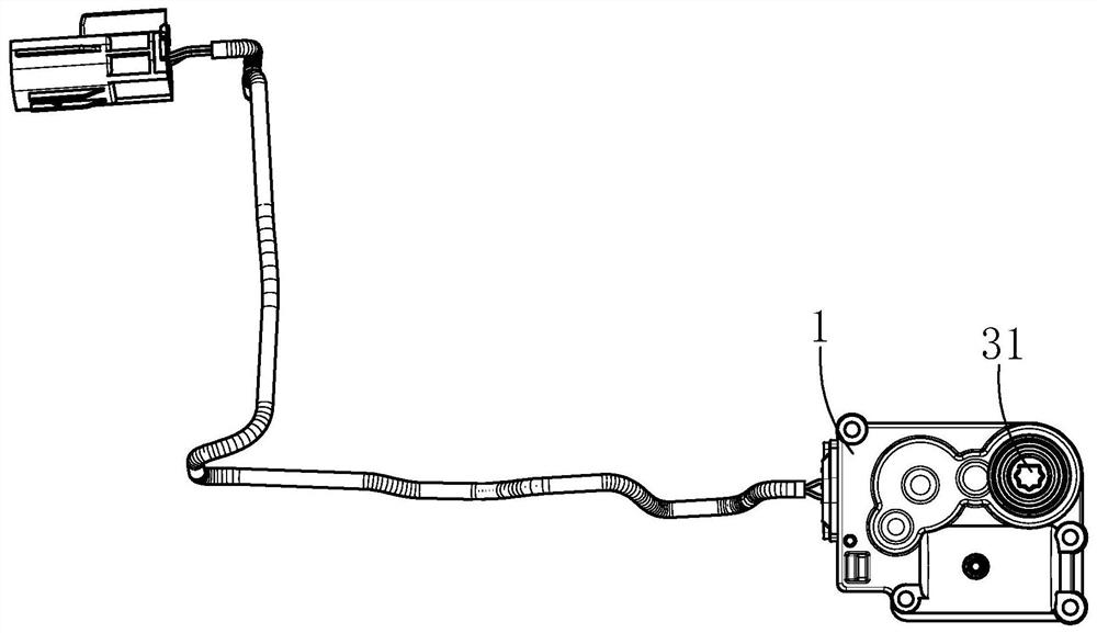
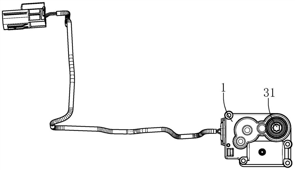
[0045] refer to Figure 1 to Figure 12 , an electric small door actuator assembly on a fuel tank cover or a charging box cover for a vehicle, comprising:

[0046] The actuator housing 1 is arranged in the vehicle body and has an inner cavity 4 opened therein. Preferably, a waterproof plug 2 is provided at the inlet end of the actuator housing 1, and a skeleton oil seal 3 is provided at the output end (at the output device) of the actuator housing 1 to improve the overall waterproof and dustproof sealing performance and ensure that the internal Normal operation of electrical accessories;

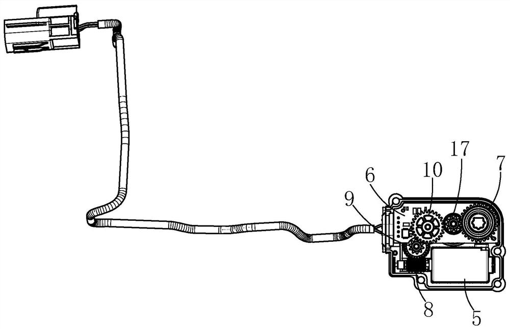
[0047] A driving mechanism, which is arranged in the inner cavity 4, and is used to provide power, preferably a motor 5;

[0048] The electronic control device is used to control the operation of the drive mechanism and is electrically connected to the driving computer. The electronic control device mainly includes an ECU circuit board 6 arranged in the actuator housing 1 to realize communi...

Embodiment 2

[0063] Compared with the technical solution of Embodiment 1, this embodiment is equipped with a motor shaft sleeve 28 and a motor stopper 29 on the output shaft of the motor 5 (drive mechanism), so as to prevent the displacement of the worm gear structure when it is subjected to a lateral force. Thereby, relevant components can be stably maintained on their working positions, and the normal operation of the whole can be ensured.

Embodiment 3

[0065] Compared with the technical solutions of the above other embodiments, this embodiment integrates a resistive position sensor 30 on the ECU circuit board 6 for monitoring and feedbacking the position of the fuel tank cover or the charging tank cover.


PUM


Abstract

An electric small door actuator assembly on a vehicle refueling tank cover or a charging tank cover comprises: an actuator shell provided with an inner cavity, a drive mechanism which provides power, an electric control device which is used for controlling the operation of the drive mechanism and is electrically connected to a driving computer, an output device which is used for driving a refueling tank cover or a charging tank cover to be opened and closed, a self-locking transmission mechanism, wherein an input end of the self-locking transmission mechanism is in transmission connection to the drive mechanism, the output end of the self-locking transmission mechanism is connected to the output device, and the self-locking transmission mechanism has a reverse self-locking function, and a clutch mechanism which is connected between the transmission mechanism and the output device and has a separation state and a connection state. When the clutch mechanism is in a joint state, the drive mechanism can drive the refueling tank cover or the charging tank cover to be opened and closed through the output device. The refueling tank cover or the charging tank cover is manually pressed to apply a certain torsion force, so that the clutch mechanism can be switched from a joint state to a separation state, the reverse self-locking function of the self-locking transmission mechanism is relieved, and the refueling tank cover or the charging tank cover is manually opened and closed.

Description

technical field [0001] The invention relates to the technical field of auto parts, in particular to an electric small door actuator assembly on a fuel tank cover or a charging tank cover for a vehicle. Background technique [0002] Nowadays, with the development of the automobile industry and the increase in the popularity of automobiles, people have higher and higher requirements for the performance of automobiles, and they also pay more attention to the speed, convenience and safety of various operations of vehicles. Therefore, automobile companies It is especially important for the improvement of vehicle structure and the application of new technologies. [0003] In the traditional structure, for the opening and closing of the small door of the fuel filler cap or the small door of the charging port cover, most of them are unlocked or locked mechanically, that is, the lock lever is fixed on the small door, and the lock sleeve is fixed on the body seat. Or pull the cable t...

Claims


Application Information

Patent Timeline
IPC IPC(8): E05B81/06E05B81/34E05B81/46E05B81/56E05B81/70E05B81/90E05B83/28
CPCE05B81/06E05B81/34E05B81/46E05B81/56E05B81/70E05B81/90E05B83/28
Inventor 孙云飞周君臣唐淼周磊
Owner NINGBO HUAKAI ELECTRONICS TECH CO LTD
Why Eureka
Try Eureka