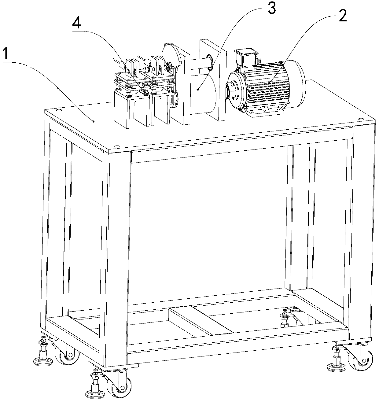
High-speed swing bearing fatigue life test device

A technology for oscillating bearings and fatigue life, which is applied in the direction of mechanical bearing testing, etc., can solve the problems of large dynamic load, large vibration noise, and high test cost, and achieve the effect of small dynamic load, low vibration noise, and reduced test cost

Pending Publication Date: 2019-05-14
LISHUI UNIV
View PDF1 Cites 15 Cited by
  • Summary
  • Abstract
  • Description
  • Claims
  • Application Information

AI Technical Summary

Problems solved by technology

But there are also the following disadvantages: a. The crank rocker mechanism is used to realize the swing motion, and the dynamic load and vibration noise are large during operation, so it is not suitable for high-speed operation; b. The static spring or oil cylinder is used to realize the loading, which cannot realize the bearing during the operation The follow-up change of the load, or the follow-up change of the load can only be realized when swinging at a low speed; c. There is no function of monitoring the change of the bearing friction torque, so the operation of the bearing cannot be reflected in real time; d. Only a single bearing can be tested, and the test cost is high

Method used


Image

  • High-speed swing bearing fatigue life test device
  • High-speed swing bearing fatigue life test device
  • High-speed swing bearing fatigue life test device

Examples


Embodiment Construction

[0029] Embodiments of the present invention are described in detail below, examples of which are shown in the drawings, wherein the same or similar reference numerals designate the same or similar elements or elements having the same or similar functions throughout. The embodiments described below by referring to the figures are exemplary and are intended to explain the present invention and should not be construed as limiting the present invention.

[0030]In describing the present invention, it should be understood that the terms "center", "longitudinal", "transverse", "length", "width", "thickness", "upper", "lower", "front", " The orientations or positional relationships indicated by "rear", "left", "right", "vertical", "horizontal", "top", "bottom", "inner", "clockwise", "counterclockwise" are based on the attached The orientation or positional relationship shown in the figure is only for the convenience of describing the present invention and simplifying the description,...


PUM


Abstract

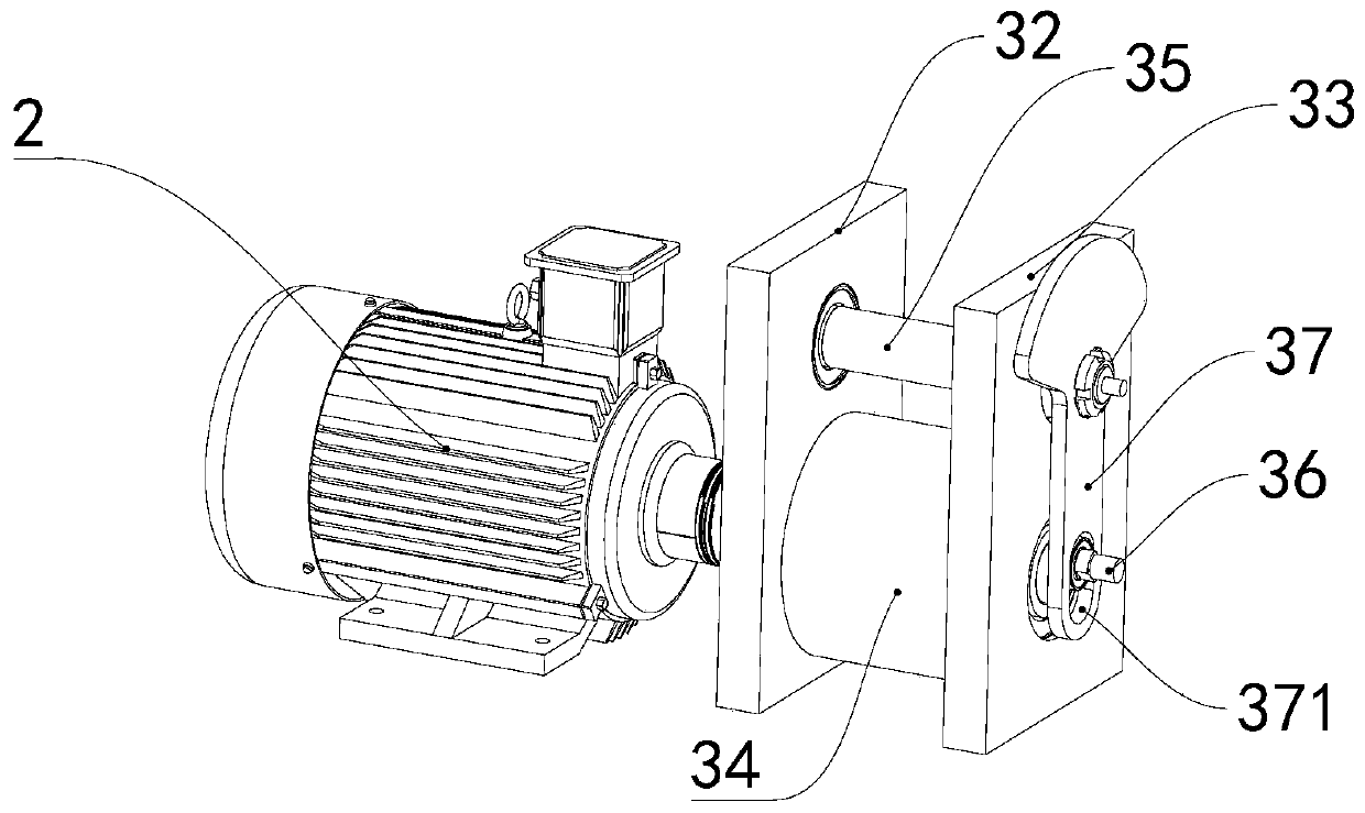
The invention discloses a high-speed swing bearing fatigue life test device. The device comprises a console, and a driving motor, a rotary swing conversion module, a plurality of test modules and testbearings which are arranged on the console, wherein jackets sleeve the test bearings; each test module comprises a radial sine pulse loading module, a friction torque monitoring module, a temperaturedetection module and a bearing supporting module; the radial sine pulse loading modules in the plurality of test modules are connected to each other; the bearing supporting modules in the plurality of test modules are connected to each other; the rotary swing conversion module is provided with a flywheel and is directly connected to a driving motor; the rotary swing conversion module simultaneously drives the test bearings to rotate and swing in a reciprocating manner and the radial sine pulse loading modules to provide pulse radial loads for the test bearings. According to the technical scheme, the friction torque change situation of the plurality of test bearings under different test conditions can be monitored in real time, so that whether the bearing has a failure condition is judged.

Description

technical field [0001] The invention belongs to the field of bearing life test, in particular to a high-speed swing bearing fatigue life test device. Background technique [0002] The existing bearing swing life test device is mainly aimed at sliding joint bearings, and the swing frequency is relatively low, generally <30 times / minute, which is not suitable for high-speed swing bearings. [0003] For example, the patent document whose publication number is CN205981688U discloses a joint bearing life testing machine, which includes an operating table and a test main part arranged on the operating table. The test main part includes a test spindle, a bearing fixture, a load loading device, a torque sensor and a transmission The two ends of the test spindle are respectively supported by the left support assembly and the right support assembly. The transmission shaft is connected to one end of the test spindle through a torque sensor. The other end of the test spindle is equip...

Claims


Application Information

Patent Timeline
Patent Type & Authority Applications(China)
IPC IPC(8): G01M13/04
Inventor 卓耀彬叶晓平林云峰
Owner LISHUI UNIV
Why Eureka
Try Eureka