Motor driving type self-casting mechanism provided with upper and lower die releasing mechanisms

A technology of motor-driven and demolding mechanism, applied in the direction of manufacturing tools, casting equipment, equipment for transporting casting molds, etc., can solve the problems of trouble and high height of casting equipment, and achieve the effect of convenient ejection and unloading and height reduction.

Inactive Publication Date: 2019-05-17
郑青松
View PDF5 Cites 1 Cited by
  • Summary
  • Abstract
  • Description
  • Claims
  • Application Information

AI Technical Summary

Problems solved by technology

[0002] In the existing casting equipment, the upper casting mold and the lower casting mold are generally fixed and pressed manually with bolts, and then the feeding guide device is manually fixed on the feeding inlet, and then the casting liquid is transferred from the feeding material through the casting equipment. Pour into the guide device for casting. After the casting is completed, the upper casting mold and the lower casting mold need to be manually disassembled, and the cast castings need to be manually taken out of the casting cavity, which is very troublesome.
[0003] Therefore, some of the existing casting equipment adopts hydraulic push to press and fix the upper casting mold and the lower casting mold up and down. The pushing oil cylinder in this type of hydraulic equipment is generally above the upper casting mold, so that the height of the casting equipment is relatively high. Some height-restricted factories or processing places are not suitable

Method used


Image

  • Motor driving type self-casting mechanism provided with upper and lower die releasing mechanisms

Examples


Embodiment Construction

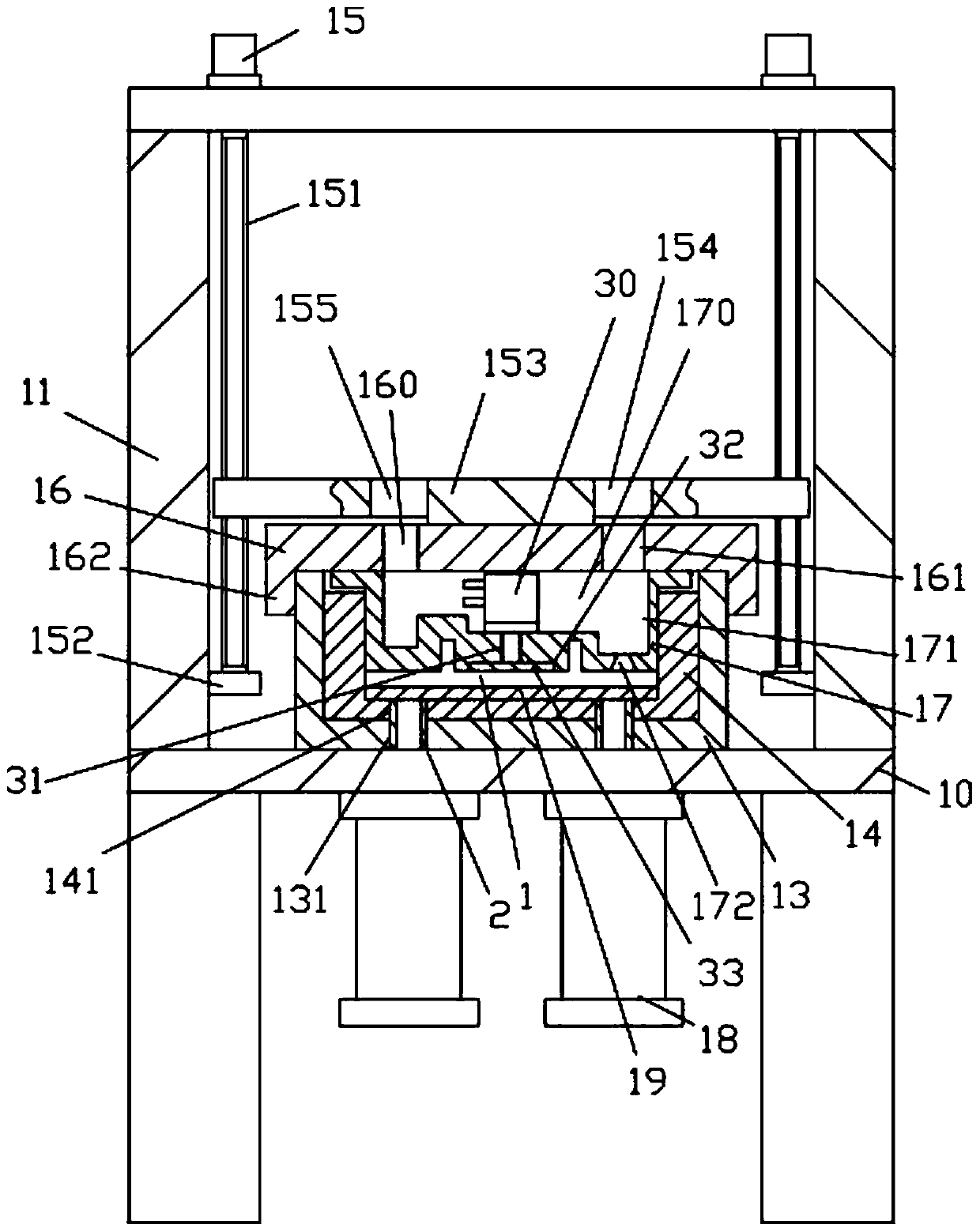
[0018] Examples, see e.g. figure 1 As shown, a motor-driven self-casting mechanism with an upper and lower demoulding mechanism includes a frame 10, an upper support frame 11 is fixed on the top surface of the top plate of the frame 10, and the left and right sides of the top plate of the upper support frame 11 The top surface is all fixed with servo motor 15, and two vertical screw rods 151 are at the both sides of the top plate of frame 10, and the bottom end of vertical screw rod 151 is hinged on two lower connection plates 152 by bearing, and lower connection plate 152 is fixed on On the lower side wall of the side support plate of the upper support frame 11, the upper end of the vertical screw rod 151 is hinged on the top plate of the upper support frame 11 through a bearing, the output shaft of the servo motor 15 is a spline shaft, and the spline shaft is inserted into the vertical In the spline hole that the top of the straight screw rod 151 has, the lifting plate 153 i...


PUM


Abstract

The invention discloses a motor driving type self-casting mechanism provided with upper and lower die releasing mechanisms. The motor driving type self-casting mechanism provided with the upper and lower die releasing mechanisms comprises a rack, wherein an upper supporting frame is fixed to the top surface of a top plate of the rack; servo motors are fixed to the top surfaces of the left side andthe right side of the top plate of the upper supporting frame; two vertical screws are positioned at the two sides of the top plate of the rack; the bottom ends of the vertical screws are hinged totwo lower connecting plates through bearings; and the lower connecting plates are fixed to the lower sidewalls of side supporting plates of the upper supporting frame. According to the motor driving type self-casting mechanism provided with the upper and lower die releasing mechanisms, the mechanism is driven through the servo motors; a compressing plate and a lower fixing housing are automaticallypressed against each other to enable fitting and fixing of an upper casting die and a lower casting die to be achieved; the upper casting die is not manually mounted and dismounted; due to the drivingof the servo motors, the height of the whole mechanism is greatly reduced, some factory houses or processing sites with limited height can perform processing conveniently, and the convenience is ensured; and meanwhile, materials can be automatically pushed through a lower pushing oil cylinder and an upper pushing oil cylinder, and thus a casted finishedproduct in a casting chamber can be pushed out and discharged.

Description

Technical field: [0001] The invention relates to the technical field of casting equipment, in particular to a motor-driven self-casting mechanism with an upper and lower demoulding mechanism. Background technique: [0002] In the existing casting equipment, the upper casting mold and the lower casting mold are generally fixed and pressed manually with bolts, and then the feeding guide device is manually fixed on the feeding inlet, and then the casting liquid is transferred from the feeding material through the casting equipment. Pour into the guide device for casting. After the casting is completed, it is necessary to manually disassemble the upper casting mold and the lower casting mold, and it is very troublesome to manually take out the casting that has been cast from the casting cavity. [0003] Therefore, some of the existing casting equipment adopts hydraulic push to press and fix the upper casting mold and the lower casting mold up and down. The pushing oil cylinder i...

Claims


Application Information

Patent Timeline
Patent Type & Authority Applications(China)
IPC IPC(8): B22D33/04B22D35/04B22D29/06
Inventor 郑青松
Owner 郑青松
Why Eureka
Try Eureka