Concrete curing box test block placing assembly and mounting structure

A curing box and concrete technology, which is applied to the field of placing components and installation structures of test blocks in concrete curing boxes, can solve the problems of inability to guarantee the stable placement state of test blocks, unable to meet the needs of diversified test blocks, etc., so as to improve the use value and convenience. effect used

Active Publication Date: 2019-05-17
GUANGXI HENGXIAN GUITONG CEMENT PROD
View PDF6 Cites 0 Cited by
  • Summary
  • Abstract
  • Description
  • Claims
  • Application Information

AI Technical Summary

Problems solved by technology

[0005] The purpose of the present invention is to provide a concrete curing box test block placement assembly and installation structure to solve the problem that some of the current placement structures proposed in the above background technology cannot ensure the stability of the placement state of the test block, and some cannot meet the use requirements of diversified test blocks The problem

Method used


Image

  • Concrete curing box test block placing assembly and mounting structure
  • Concrete curing box test block placing assembly and mounting structure
  • Concrete curing box test block placing assembly and mounting structure

Examples


Embodiment 1

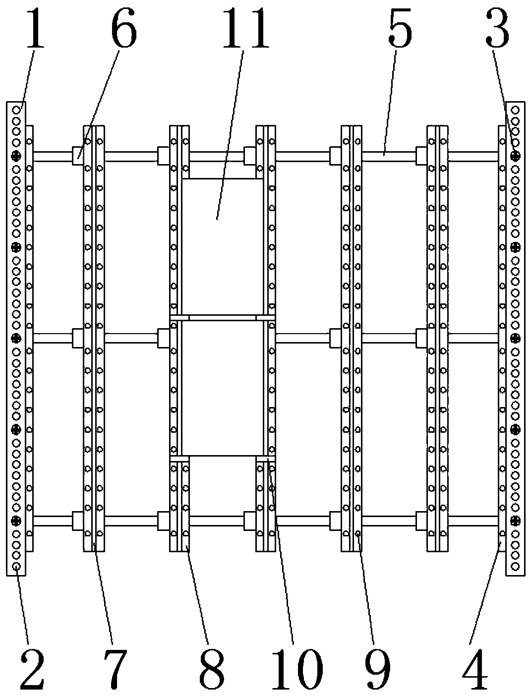
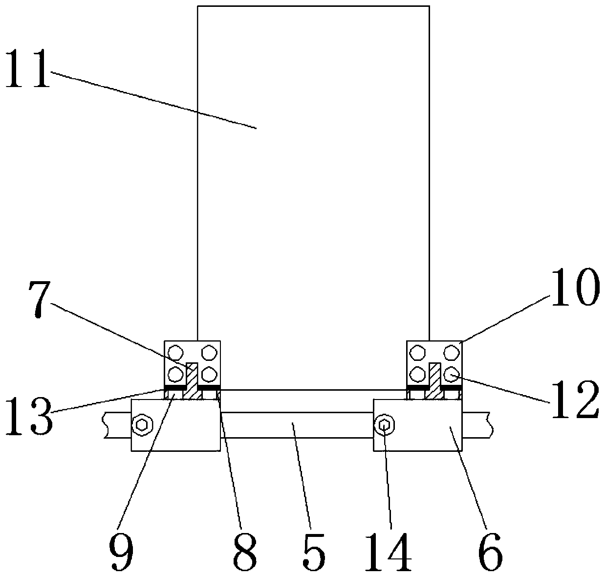
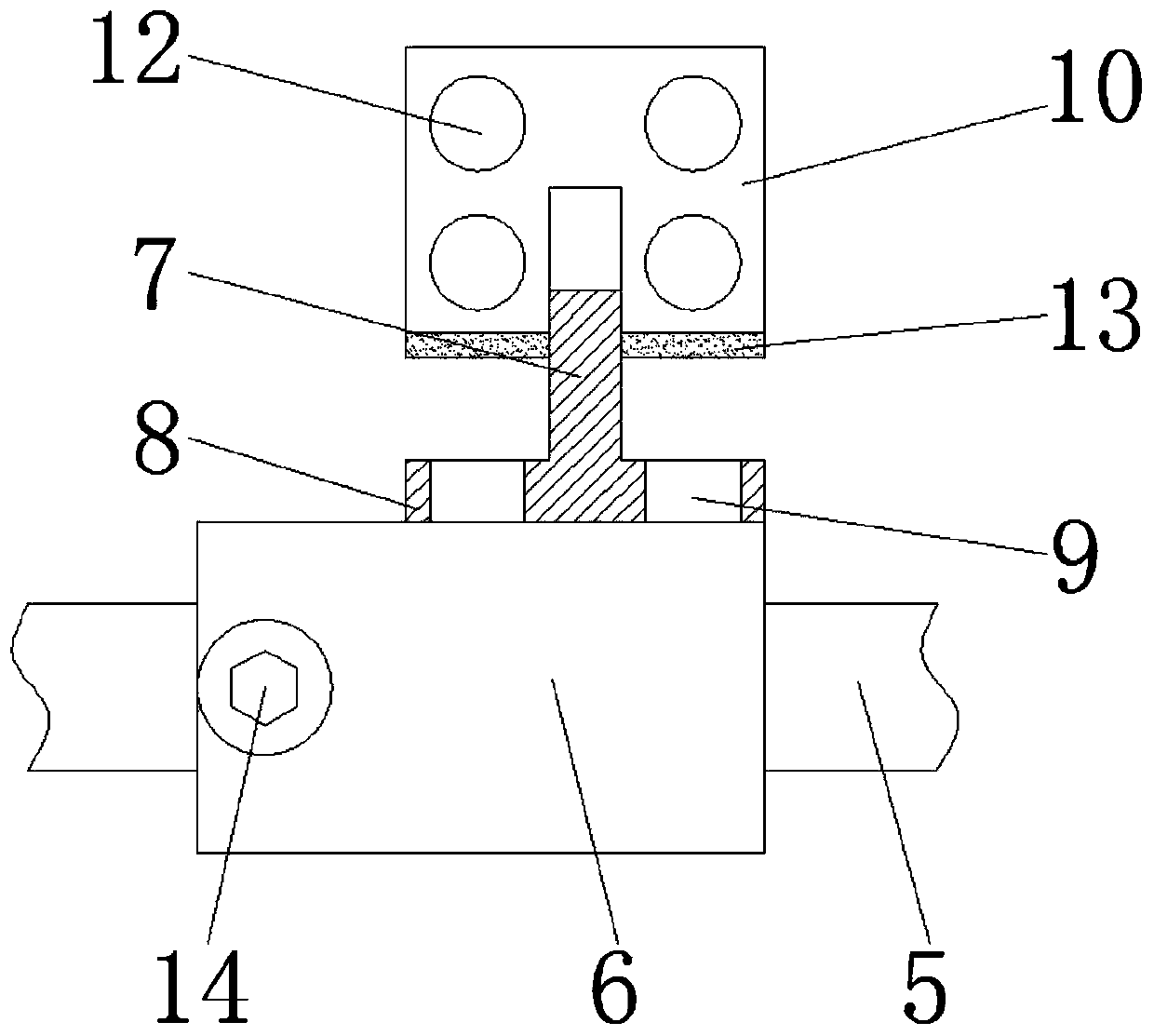
[0030] see Figure 1-7 , a concrete curing box test block placement assembly of the present embodiment, including a limit piece 1, a ball 2, a first fixing bolt 3, a first support piece 4, a support rod 5, a connecting seat 6, a first spacer 7, The second support piece 8, the first through hole 9, the second spacer 10, the concrete test block 11, the second through hole 12, the magnet piece 13, the second fixing bolt 14, the third through hole 15, the sliding support body 16, The fourth through hole 17 and the fixing groove 18, the lower side of the limiting piece 1 is connected with a sliding support body 16, and a ball 2 is arranged between the sliding supporting body 16 and the limiting piece 1, the limiting piece 1 and the sliding supporting body 16 The first support piece 4 and the support rod 5 are fixed on the inner side of the sliding support body 16, and the support rod 5 is located on the lower side of the first support piece 4, and the support rod 5 is connected wit...

Embodiment 2

[0039] see Figure 1-7 , a concrete curing box test block installation structure of the present embodiment, including a limit piece 1, a ball 2, a first fixing bolt 3, a first support piece 4, a support rod 5, a connecting seat 6, a first spacer 7, The second support piece 8, the first through hole 9, the second spacer 10, the concrete test block 11, the second through hole 12, the magnet piece 13, the second fixing bolt 14, the third through hole 15, the sliding support body 16, The fourth through hole 17 and the fixing groove 18, when using the concrete curing box to place the concrete test block 11, it is necessary to install the placement structure of the concrete test block 11 in the concrete curing box to facilitate the placement of the concrete test block 11 First, the ball 2 needs to be placed between the limiting piece 1 and the sliding support body 16, and then the limiting piece 1 and the sliding supporting body 16 are fixed together by the first fixing bolt 3, and ...


PUM

PropertyMeasurementUnit
Thicknessaaaaaaaaaa

Abstract

The invention discloses a concrete curing box test block placing assembly and a mounting structure. The concrete curing box test block placing assembly comprises a limiting piece, a supporting rod anda sliding supporting main body. The sliding supporting main body is connected to the lower side of the limiting piece, a rolling ball is arranged between the sliding supporting main body and the limiting piece, a first supporting piece and a supporting rod are fixed to the inner side of the sliding supporting main body, the supporting rod is located on the lower side of the first supporting piece, a second through hole is formed in a second interval piece, the lower end of the second interval piece is connected with a second supporting piece through a magnet piece, a fixed groove is formed inthe limiting piece, and a fixed bolt is arranged in the fixed groove. According to the concrete curing box test block placing assembly and the mounting structure, disassembly and assembly of the supporting rod, a first interval piece and the second supporting piece are facilitated, so that the supporting size of the structure on test blocks is facilitated, the structure can be used for the test blocks with different sizes, and the using value of the structure is improved.

Description

technical field [0001] The invention relates to the technical field of concrete curing boxes, in particular to a concrete curing box test block placement component and installation structure. Background technique [0002] The concrete curing box is used for constant temperature and humidity standard curing of concrete specimens. It is an ideal equipment for laboratories and quality inspection centers to maintain concrete specimens. In the use of concrete curing boxes, specific test blocks are usually required to match the concrete curing box. Use, but the state of the test block in the concrete curing box also needs to have certain restrictions, which requires the use of some placement structures to match the use of the test block, but some structures used to place the test block are too simple to use; [0003] For example, some placement structures simply arrange the test blocks without restricting the structure of the test blocks, so that it is impossible to avoid the disp...

Claims


Application Information

Patent Timeline
IPC IPC(8): B28B11/24G01N1/28
Inventor 不公告发明人
Owner GUANGXI HENGXIAN GUITONG CEMENT PROD
Why Eureka
Try Eureka