
Flexible space solar panel

A technology of solar sail panels and solar panels, applied in the field of solar sail panels, can solve the problems of uncontrollable unfolding process, large folded volume, and difficult to predict unfolding trajectory, so as to achieve controllable unfolding process, large unfolding degree, and favorable collection Effect

Active Publication Date: 2019-05-17
HARBIN INST OF TECH
View PDF6 Cites 6 Cited by
  • Summary
  • Abstract
  • Description
  • Claims
  • Application Information

AI Technical Summary

Problems solved by technology

[0004] In view of this, the present invention aims to propose a flexible space solar panel to solve the problems in the prior art such as large volume when folded, uncontrollable unfolding process and difficult to predict the unfolding trajectory.

Method used


Image

  • Flexible space solar panel
  • Flexible space solar panel
  • Flexible space solar panel

Examples


Embodiment 1

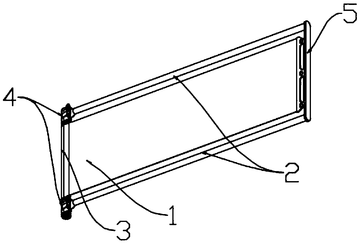
[0036] This embodiment provides a flexible space solar panel, combined with figure 1 As shown, it includes a solar energy collection device 1, a flexible deployment device 2, a mandrel 3, a deployment control device 4 and a bracket 5. The solar energy collection device 1 is arranged on a spacecraft. Before the spacecraft enters a predetermined orbit, the solar energy collection device 1 needs to be folded. Ensure a small volume to prevent the spacecraft from being damaged by friction with the atmosphere or violent vibration during lift-off. After the spacecraft enters the predetermined orbit, the solar energy collection device 1 needs to be expanded to ensure a large external area, so that the solar energy collection device 1 1. It can receive the sun’s irradiation with the largest area in space for solar power generation. In this embodiment, the solar energy collection device 1 is folded in a curled shape when it is folded. shape, the unfolding process is gentle, and the volu...

Embodiment 2

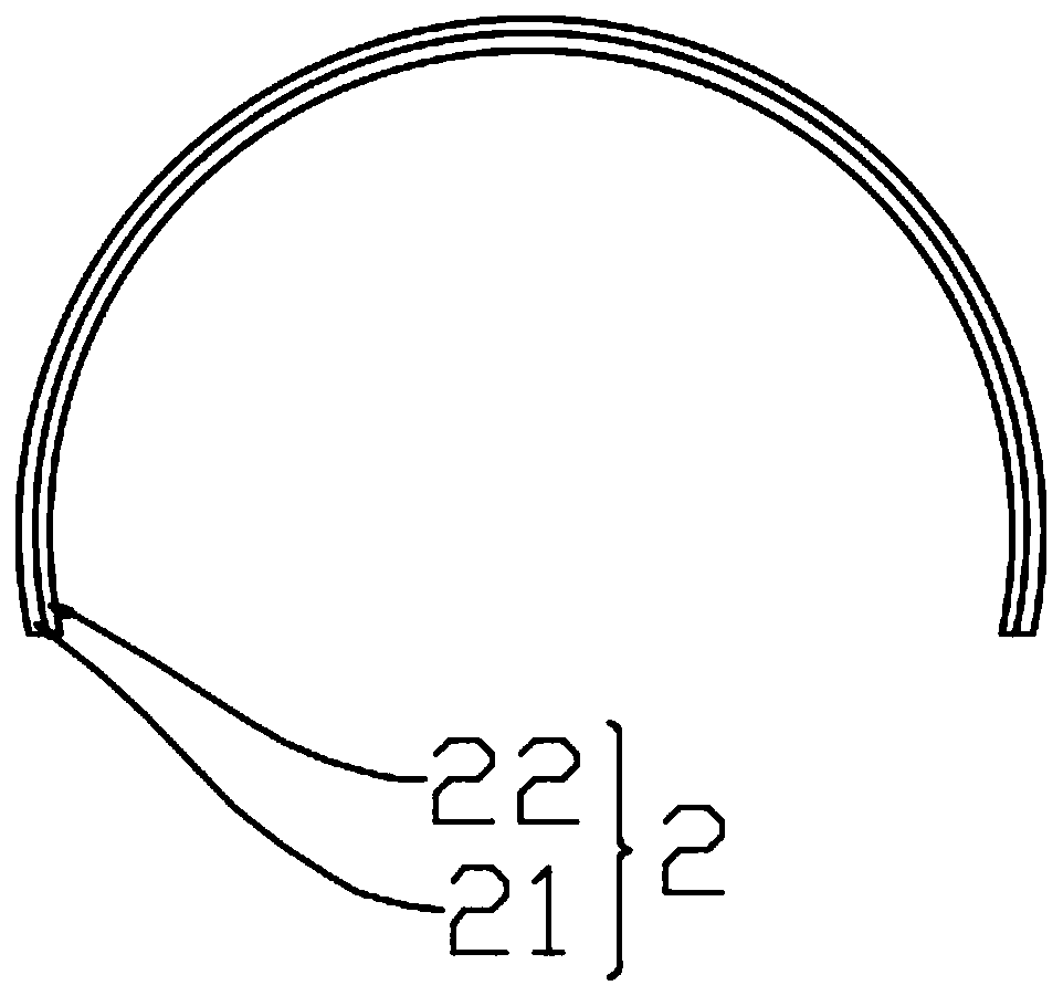
[0046] The difference between this embodiment and Embodiment 1 is that when the expandable beam device 21 is made of shape memory polymer material, combined with Figure 7 As shown, the flexible deployment device 2 also includes a heating device 22, and the heating device 22 includes a heater. The heater is arranged at the port 44 of the deployment control mechanism 4, that is, only at the port 44 is the shape memory polymer material changed from crimped to Heating is carried out locally in a stretched state, and the implementation of local heating and expansion is as follows Figure 7 As shown, a heater is provided at the position of the transition part where the flexible deployment device 2 is unfolded in a curled shape. The heater can transfer the internally generated heat source to the transition part of the flexible deployment device 2 by means of heat flow and radiation, similar to the principle of a blower. In this way, only the part of the structure that is undergoing ...


PUM


Abstract

The invention provides a flexible space solar panel and relates to the technical field of solar panels. The flexible space solar panel comprises a solar collection device, a flexible unfolding device,a mandrel, an unfolding control device and a bracket, wherein the solar collection device is applicable to coiling and solar power generation; the flexible unfolding device is suitable for driving the solar collection device to be coiled, folded and unfolded; both the solar collection device and the flexible unfolding device are wound on the mandrel when being coiled and folded up; the unfoldingcontrol device is suitable for controlling the flexible unfolding device to unfold along a plane parallel to the tangent plane of the mandrel; the bracket is suitable for connecting the solar collection device and a spacecraft. According to the flexible space solar panel provided by the invention, a solar panel framework structure which is controllable in unfolding process and small in spacecraftimpact is manufactured by using a shape memory polymer composite material, integral design and manufacturing of a solar panel are achieved, a large-size solar panel can be coiled and folded up in a launching process, the solar panel is light in weight, and meanwhile, the unfolding reliability can be improved.

Description

technical field [0001] The invention relates to the technical field of solar sail panels, in particular to a flexible space solar sail panel. Background technique [0002] Space solar panels are mainly used in the power supply system of space vehicles such as space capsules, satellites, and alien probes. Traditional solar panels are mostly rigid structures, and multiple panels are connected by mechanical structures. Before being carried into space, the solar panel is folded through the mechanical structure of the connection part to reduce the launch volume. After being transported to the predetermined position by the launch vehicle, the mechanical connection structure is used to drive and expand the solar panel to increase the area of ​​the panel and enter the working state. However, the mechanical There are many problems with solar panels: the mechanical connection structure is complex and heavy; the use of multi-level mechanical connection structures in series and paralle...

Claims


Application Information

Patent Timeline
Patent Type & Authority Applications(China)
IPC IPC(8): B64G1/44H02S30/20
CPCY02E10/50
Inventor 冷劲松刘彦菊明光清戴雯煦刘立武
Owner HARBIN INST OF TECH
Learn More